
Streak camera reflection type off-axis optical coupling device

A streak camera and optical coupling technology, applied in the field of spectroscopic instruments and spectroscopy, can solve the problems of large number of reflective surfaces, complex structure, inconvenient adjustment, etc., and achieve the effects of wide spectral range, good imaging quality and simple structure

Active Publication Date: 2011-11-23
INST OF SEMICONDUCTORS - CHINESE ACAD OF SCI
View PDF6 Cites 1 Cited by
  • Summary
  • Abstract
  • Description
  • Claims
  • Application Information

AI Technical Summary

Problems solved by technology

However, due to the dispersion of the lens, the range of the imaging band of the transmissive optical coupling device is small, and the shorter the wavelength, the smaller the range of the clear imaging band.
In addition, due to the limited materials suitable for making lenses in the deep ultraviolet band and the immature coating process on the surface of the lens, the transmissive optical coupling device is not suitable for applications in the deep ultraviolet or shorter bands.
The reflective optical coupling device currently used has a large number of reflective surfaces and a complex structure, resulting in large light loss, inconvenient adjustment, and high cost

Method used


Image

  • Streak camera reflection type off-axis optical coupling device
  • Streak camera reflection type off-axis optical coupling device
  • Streak camera reflection type off-axis optical coupling device

Examples


specific Embodiment approach

[0026] Please refer to figure 1 The optical path diagram of the reflective off-axis optical coupling device of the streak camera is shown, and the specific implementation method is as follows:

[0027] The optical path of the reflective off-axis optical coupling device of the streak camera is composed of a collimating mirror 11 and a focusing mirror 12 . The slit 13 is placed on the focal plane of the collimating mirror 11, so that the divergent light emitted from the slit 13 irradiates the collimating mirror 11 and is converted into parallel light. And it is required that the slit 13 is located outside the optical axis of the collimating mirror 11 to ensure that the light beam is not blocked by the focusing mirror 12 before reaching the collimating mirror 11 . The parallel light collimated by the collimating mirror 11 is irradiated onto the focusing mirror 12 , after passing through the focusing mirror 12 the parallel light becomes converging light, and finally irradiates on...


PUM


Abstract

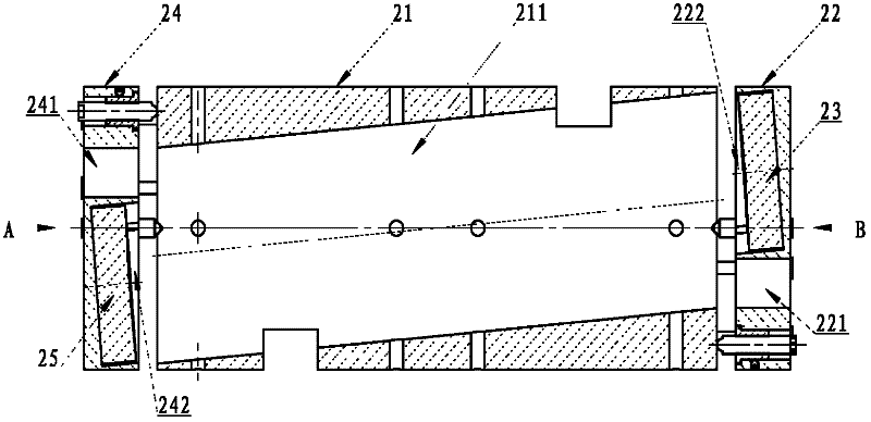
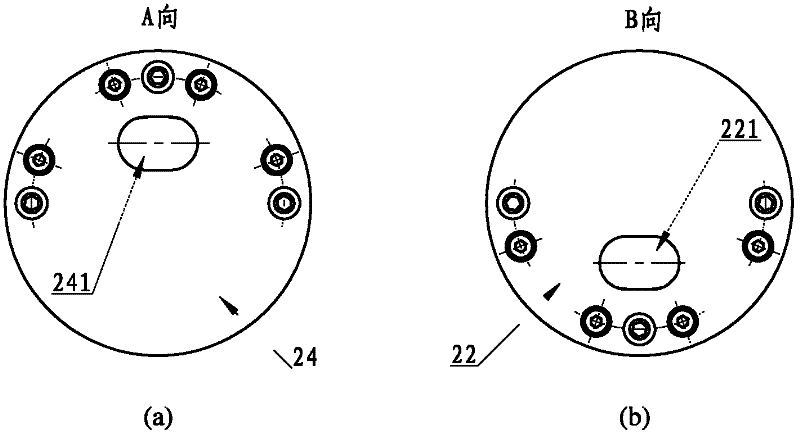
A streak camera reflection type off-axis optical coupling device comprises a drawtube, a collimating mirror seat, a collimating mirror, a focusing mirror seat and a focusing mirror, wherein the center of the drawtube is provided with a cylindrical hole; the collimating mirror seat is a cylinder, one side of the center of the collimating mirror seat is provided with a light outlet, the larger part on the other side of the light outlet is provided with a round groove, a preset angle is formed between the round groove and the central axis, the collimating mirror seat is fixed on one end of the drawtube through screws, the screws are used to adjust the relative positions of the collimating mirror seat and the drawtube; the collimating mirror is in the round groove of the collimating mirror seat; the focusing mirror seat is a cylinder, one side of the center of the focusing mirror seat is provided with a light inlet, the larger part on the other side of the light inlet is provided with a round groove, a preset angle is formed between the round groove and the central axis, the focusing mirror seat is fixed on the other end of the drawtube through screws, and the screws are used to adjust the relative positions of the focusing mirror seat and the drawtube; and the focusing mirror is in the round groove of the focusing mirror seat.

Description

technical field [0001] The invention belongs to the field of spectroscopic instruments and spectroscopic technology, in particular to a reflective off-axis optical coupling device for a streak camera. Background technique [0002] Streak camera is an instrument for measuring optical time-varying signals. It has the advantages of high sensitivity (photon meter level), high time resolution (up to picosecond and sub-picosecond level), and multi-wavelength simultaneous measurement. It is widely used in Ultrashort pulse light experiments, time-resolved spectroscopy, etc. When the streak camera is in use, an optical coupling device is usually required to couple the measured optical signal into the streak camera and irradiate it on the photocathode of the streak tube. The photocathode uses the photoelectric effect to convert photons into electrons. Currently, optical coupling devices for streak cameras mainly include two types, one is a transmissive optical coupling device using m...

Claims


Application Information

Patent Timeline
Patent Type & Authority Applications(China)
IPC IPC(8): G01J3/02
Inventor 金鹏王占国
Owner INST OF SEMICONDUCTORS - CHINESE ACAD OF SCI
Learn More