Optical lens

An optical lens and sub-light technology, applied in the optical field, can solve the problem of inconvenient processing of large screens, and achieve the effect of improving processing efficiency and reducing manufacturing difficulty.

Pending Publication Date: 2019-07-23
ANHUI EASPEED TECHNOLOGY CO LTD
View PDF1 Cites 1 Cited by
  • Summary
  • Abstract
  • Description
  • Claims
  • Application Information

AI Technical Summary

Problems solved by technology

[0004] In order to solve the problem that the existing optical lens is inconvenient when processing a large screen, the present invention provides an optical lens that is convenient for processing a large screen

Method used


Image

  • Optical lens
  • Optical lens
  • Optical lens

Examples


Embodiment Construction

[0036] Embodiments of the present invention are described in detail below, examples of which are shown in the drawings, wherein the same or similar reference numerals designate the same or similar elements or elements having the same or similar functions throughout. The embodiments described below by referring to the figures are exemplary only for explaining the present invention and should not be construed as limiting the present invention.

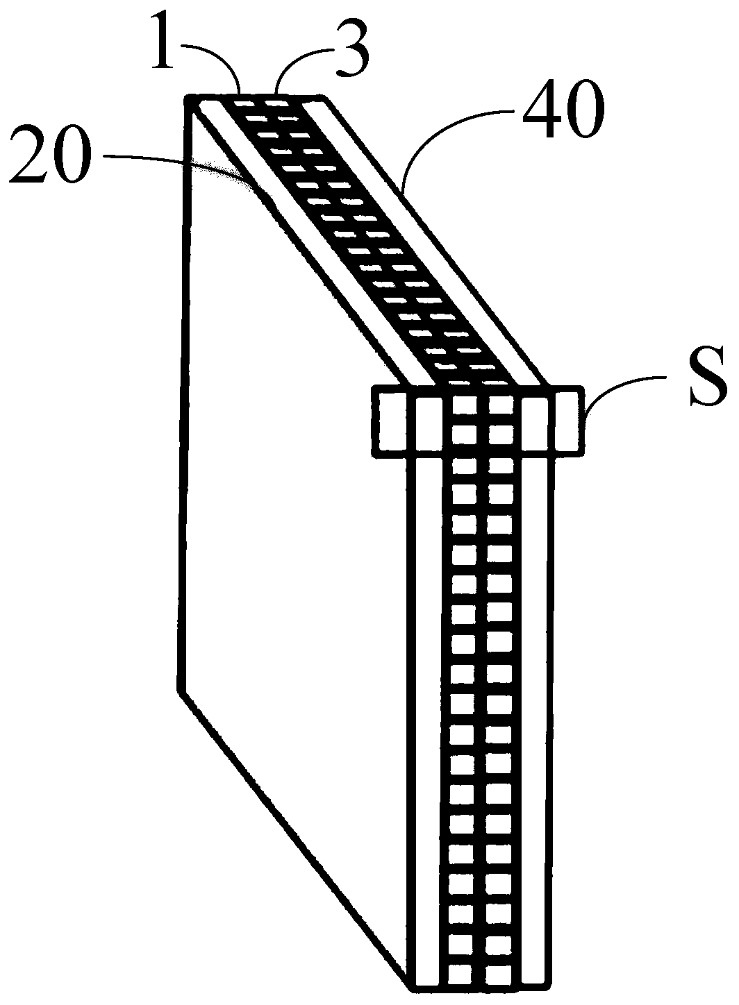
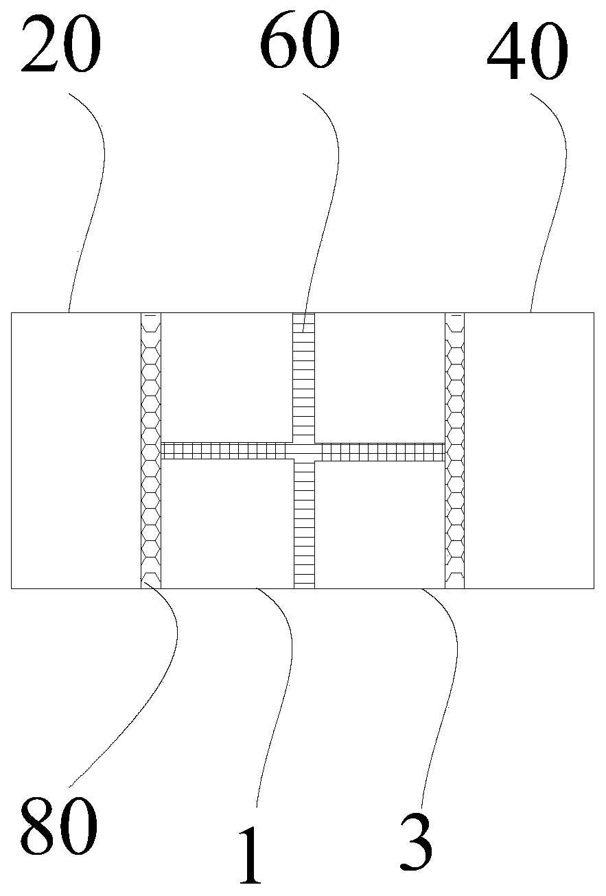
[0037] see Figure 2-3 , an optical lens according to an embodiment of the present invention, which includes a first glass window 20, a second glass window 40, a first optical waveguide array 1, and a second optical waveguide array 3 adapted to the first optical waveguide array 1, wherein,

[0038]The first glass window 20 and the second glass window 40 are oppositely arranged and both have two optical surfaces; The two adhesives 80 are bonded, and the side of the first glass window 20 away from the first optical waveguide array 1 and t...


PUM


Abstract

The invention discloses an optical lens, and aims to solve the problem of inconvenience in processing large screens with an existing optical lens. The optical lens comprises a first glass window, a second glass window, a first optical waveguide array and a second optical waveguide array, wherein the first optical waveguide array and the second optical waveguide array include at least one optical waveguide array respectively; each optical waveguide array unit comprises at least one obliquely-arranged optical waveguide; and the upper and lower surfaces of the optical waveguides are provided withreflecting layers, and the waveguide directions of corresponding parts in the first and second optical waveguide arrays are perpendicular to each other. By splicing the optical waveguides with the optical waveguide array units and splicing the optical waveguide array units with the first and second optical waveguide arrays, the processing of large screens is skillfully converted into splicing ofvarious types of optical waveguides, thereby lowering the manufacturing difficulty to a certain extent and improving the processing efficiency.

Description

technical field [0001] The present invention relates to the field of optics, in particular, the present invention relates to an optical lens. Background technique [0002] With the development of imaging display technology, the requirements for imaging characteristics are constantly improving. A higher resolution is required to ensure the clarity of the observed picture while meeting the requirement of small distortion. Existing imaging technologies mainly use spherical, aspheric, Fresnel and other lenses for imaging. Limited by the field of view and aperture, there are optical aberrations such as spherical aberration, coma, astigmatism, field curvature, distortion, and chromatic aberration. [0003] see figure 1 , part of the solution, such as the Chinese invention patent application number 201480005418.X, discloses a method for manufacturing a light control panel with light reflection parts arranged in parallel. The technical scheme of the control panel and the optical ...

Claims


Application Information

Patent Timeline
Patent Type & Authority Applications(China)
IPC IPC(8): G02B6/10G02B6/124
CPCG02B6/10G02B6/124G02B2006/12038G02B2006/12102
Inventor 范超韩东成
Owner ANHUI EASPEED TECHNOLOGY CO LTD
Why Eureka
Try Eureka