
Tension force transducer

A technology of force measuring sensor and installation part, applied in the direction of measuring force, instrument, measuring device, etc., can solve the problems of sample slippage, low work efficiency, large workload, etc., to eliminate ring effect, improve work efficiency, and reduce workload Effect

Active Publication Date: 2014-01-15
AUTOMOBILE RES INST OF TSINGHUA UNIV IN SUZHOU XIANGCHENG
View PDF3 Cites 6 Cited by
  • Summary
  • Abstract
  • Description
  • Claims
  • Application Information

AI Technical Summary

Problems solved by technology

The former needs to paste strain gauges when measuring each specimen, which has a large workload and low work efficiency, and the test of different specimens is not the same strain gauge, and the consistency of the measurement conditions is poor. At the same time, the test usually uses prism or rectangle Jaw fixture, and clamp the sample by tightening the connecting screw. Too tight will cause damage to the test piece in the jaw, and too loose will cause the sample to slip in the fixture. It is difficult to control the clamping force. It brings certain errors to the test results; the latter is connected to the sensor on the specimen fixture, the sensor has a complex structure, large mass, and high cost, and the impact excitation effect (ie, ring effect) in the dynamic tensile test is serious, so the measured force poor response

Method used


Image

  • Tension force transducer
  • Tension force transducer
  • Tension force transducer

Examples


Embodiment Construction

[0017] The present invention will be further described below in conjunction with the accompanying drawings.

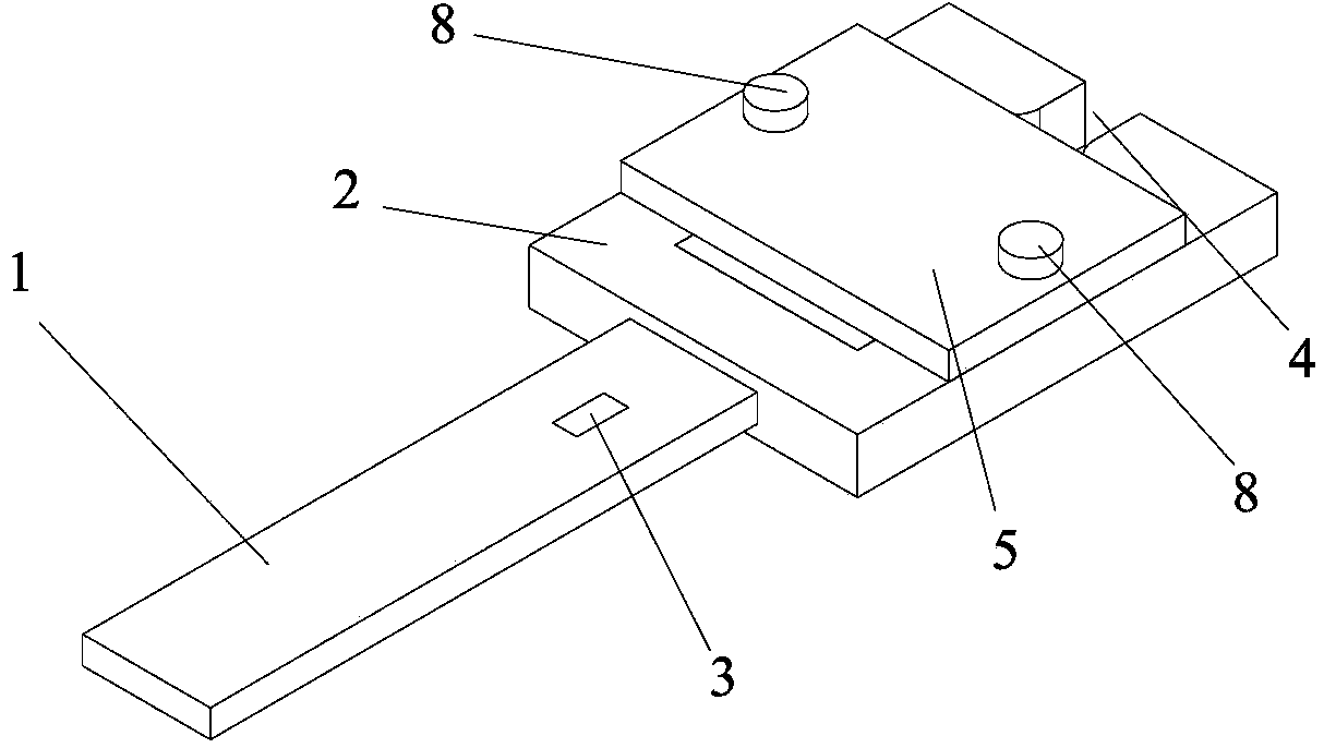
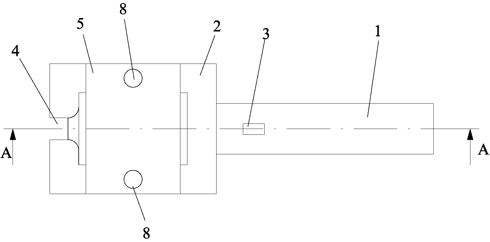
[0018] as attached Figure 1~3 As shown, a tensile force sensor includes a force-measuring part 1, an installation part 2 connected to the force-measuring part 1 for installing a test piece, a strain gauge 3 pasted on the surface of the force-measuring part 1, and measuring The force part 1 and the installation part 2 are of an integrated structure. The center line of the force measuring part 1 in the thickness direction is in line with the center line of the installation part 2 in the thickness direction. The installation part 2 is provided with a groove for placing the test piece. The groove is on the same side as the strain gauge 3, and a notch 4 is provided on the other end of the installation part 2 and on the extension line in the length direction of the force measuring part 1. The notch 4 communicates with the groove, and the width of the notch 4 is smaller than...


PUM


Abstract

The invention relates to a tension force transducer which is mainly used for testing tension mechanical properties of materials, and comprises a force measurement part, a mounting part for mounting a test piece, and a strain gage pasted on the surface of the force measurement part, wherein one end of the mounting part is connected with the force measurement part; the force measurement part and the mounting part are in an integral structure; a center line of the force measurement part in the thickness direction and a center line of the mounting part in the thickness direction are in the same straight line; the mounting part is provided with a groove for placing the test piece; the groove and the strain gage are located on the same side; a notch is formed at the other end of the mounting part and located in an extension line in the length direction of the force measurement part; the notch is communicated with the groove; the width of the notch is less than that of the groove; and the test piece extends out of the mounting part through the notch. The tension force transducer further comprises a cover plate arranged above the groove, wherein the cover plate is clung to and fixedly connected with the mounting part by a plurality of fasteners. The tension force transducer is small in size, simple in structure, low in cost and good in test effect.

Description

technical field [0001] The invention belongs to the field of testing the tensile mechanical properties of materials, is applied to the testing industry of the tensile mechanical properties of materials, and specifically relates to a tensile force sensor. Background technique [0002] Accurate force measurement is a critical issue in tensile testing of metals, composites, plastics, etc. The existing force measurement is mainly by pasting strain gauges on the test piece or connecting force sensors on the test piece fixture, and measuring the force response signal through the tensile test. The former needs to paste strain gauges when measuring each specimen, which has a large workload and low work efficiency, and the test of different specimens is not the same strain gauge, and the consistency of the measurement conditions is poor. At the same time, the test usually uses prism or rectangle Jaw fixture, and clamp the sample by tightening the connecting screw. Too tight will cau...

Claims


Application Information

Patent Timeline
Patent Type & Authority Applications(China)
IPC IPC(8): G01N3/08G01L1/22G01N3/02
Inventor 夏勇赖兴华马令晨林少挺曾龙朱俊儿王磊周青
Owner AUTOMOBILE RES INST OF TSINGHUA UNIV IN SUZHOU XIANGCHENG
Learn More