Document image reading device

A document image and reading device technology, applied in the direction of image communication, electrical components, etc., can solve the problems of small area of ​​the document reading area 15, inconsistency, increase the time for the document to be read and image, and meet the needs of improvement Strictly maintain the feeding speed and improve the effect of poor scanning efficiency

Inactive Publication Date: 2014-01-15
PRIMAX ELECTRONICS LTD
View PDF6 Cites 9 Cited by
  • Summary
  • Abstract
  • Description
  • Claims
  • Application Information

AI Technical Summary

Problems solved by technology

[0005] Furthermore, there is a document feeding channel 13 under the document table 12, and each single document P1 placed on the paper tray 14 will be fed into the feeding channel 13 and transported to the document reading area at the center of the document table 12. 15 for the image capture device 11 to take images. However, due to the narrow area of ​​the document reading area 15, only a partial image of the document P1 can be obtained for each shot, so the image capture device 11 must scan the file P1 during the moving process of the document P1. Multiple shots are required to obtain a complete image of file P1
[0006] As can be seen from the above description, if the user wants to use the document image reading device 1 and can read a complete image of a single document by taking one shot, the document must be manually placed on the document table 12 for the image capture device 11 to take pictures. And when the quantity of documents is large, the user must also manually place multiple documents one by one on the document table 12 to implement, which is not in line with convenience; moreover, if the user wants to use the document image reading device 1 and its The function of automatic paper feeding to capture the images of all documents, so although manual operation can be avoided, it increases the time for each document to be read

Method used


Image

  • Document image reading device
  • Document image reading device
  • Document image reading device

Examples


Embodiment Construction

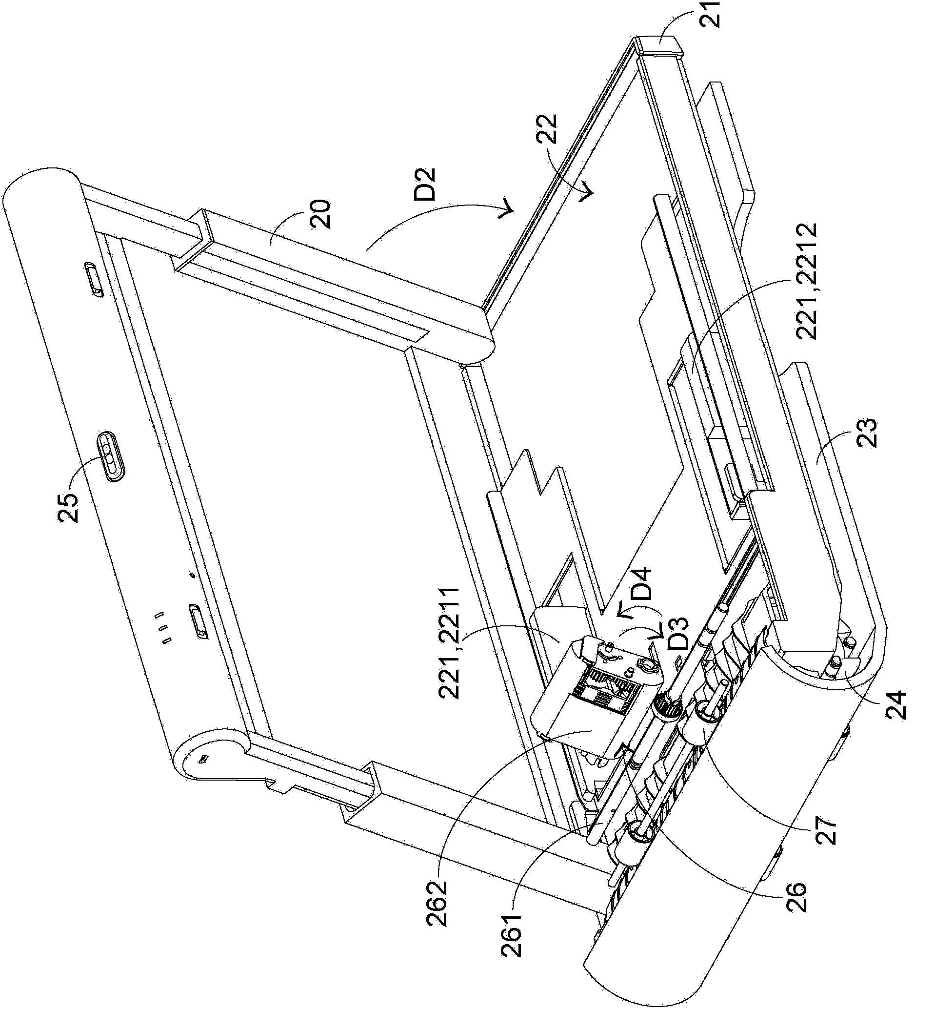
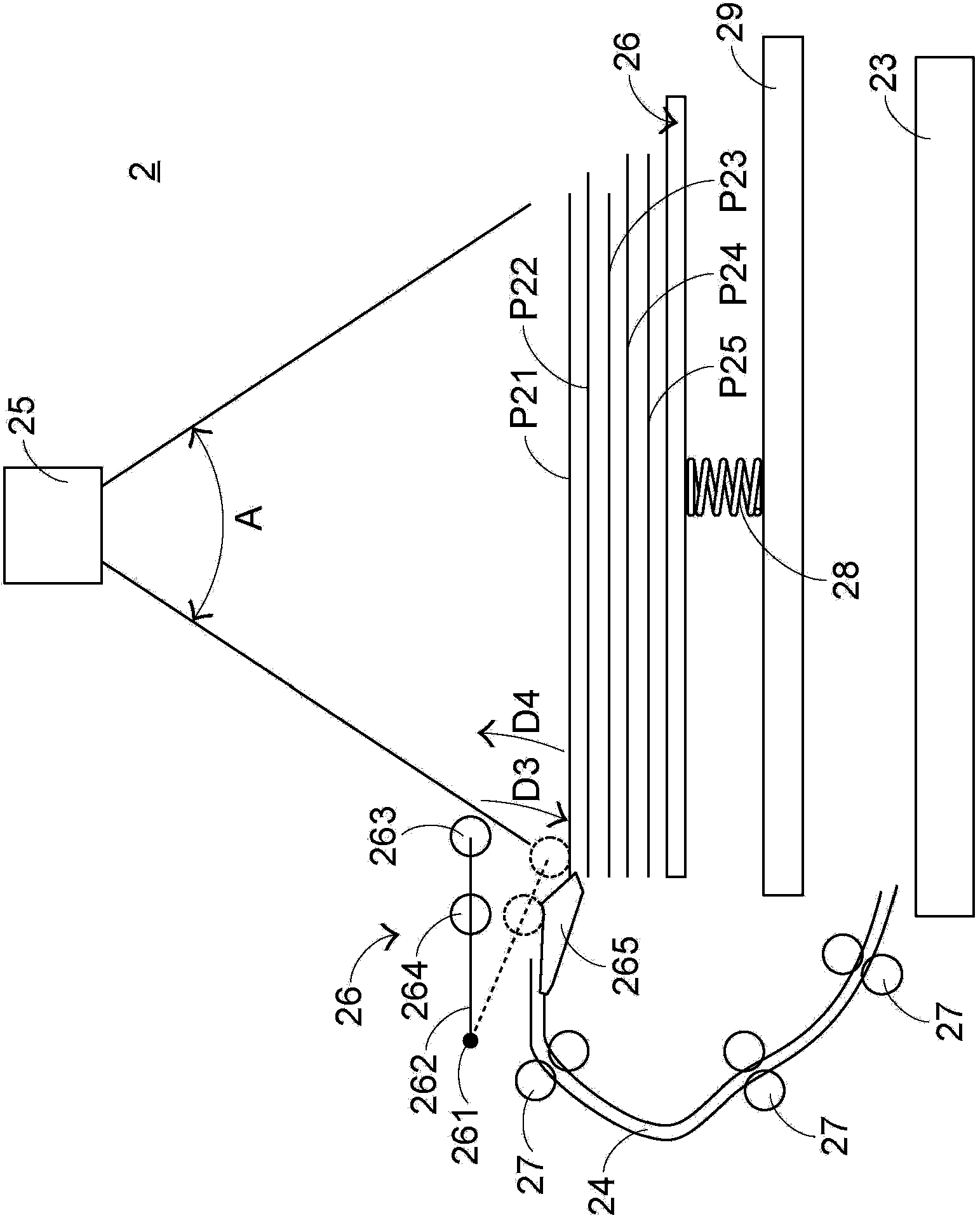
[0061] see figure 2 and image 3 , figure 2 It is a partial structural diagram of the document image reading device in the first preferred embodiment of the present invention, image 3 for figure 2A schematic diagram of the operation of the document image reading device shown. The document image reading device 2 includes a housing 21, a document input tray 22, a document output tray 23, a paper feeding channel 24, an image extraction device 25, a paper picking module 26, a transmission roller set 27, an elastic member 28 and a fixed laminate 29; wherein, the document output tray 23 is located below the document input tray 22, and the paper feeding channel 24 is connected between the document input tray 22 and the document output tray 23, and the paper picking module 26 is arranged on the document feeding The vicinity of the cassette 22 is used to sequentially feed multiple documents P21~P25 placed on the document input tray 22 into the paper feeding channel 24, and the ...


PUM


Abstract

The invention provides a document image reading device which comprises a document paper feeder box, a document paper-out box, a paper feed channel, an image extraction device, a paper fetching module and a transmission-roller module. The document paper-out box is arranged below the document paper feeder box, or the document paper-out box is disposed above the document paper feeder box. When a document on the document paper feeder box is shot by the image extraction device, the paper fetching module feeds the document into the paper feed channel, and the transmission-roller module transmits the document to the document paper-out box. The document image reading device can rapidly and fully automatically scan multiple documents on the document paper feeder box in order. Thus, the defect that a present paper-feed scanner has poor scanning efficiency and needs to strictly maintain paper feed speed is improved effectively, and the problem that present document image reading devices require manual operation due to no automatic paper feed function is solved.

Description

technical field [0001] The invention relates to a photographic image reading device, in particular to a document image reading device with automatic paper feeding function. Background technique [0002] The main function of the scanning device is to extract images and convert the content of paper documents into electronic files by scanning, so as to facilitate user transmission, organization or storage. Most of the traditional scanning devices obtain a complete image of the document through a linear scanning method, that is, drive the document to pass through the fixed scanning module at a constant speed to complete the scanning action, or keep the document fixed and make the scanning module The scanning action is completed by moving from one end of the file to the other end at a constant speed. The above-mentioned scanning method should be known to those skilled in the art, and will not be repeated here. [0003] The defect of the existing scanning device is that if the us...

Claims


Application Information

Patent Timeline
Patent Type & Authority Applications(China)
IPC IPC(8): H04N1/04H04N1/10
Inventor 管建国潘永太
Owner PRIMAX ELECTRONICS LTD
Why Eureka
Try Eureka