
Intelligent water pumping experiment system

A pumping test, intelligent technology, applied in control/regulation systems, material inspection products, non-electric variable control, etc., can solve problems such as failure to successfully complete the pumping test, weak performance of the pump screen and pump, affecting the service life of the pump, etc. Achieve rich and accurate hydrogeological parameters, reduce the difficulty of pump lifting, and achieve the effects of precise automatic control

Active Publication Date: 2019-10-15
CHONGQING INST OF GEOLOGY & MINERAL RESOURCES
View PDF14 Cites 1 Cited by
  • Summary
  • Abstract
  • Description
  • Claims
  • Application Information

AI Technical Summary

Problems solved by technology

At present, the groundwater drilling and pumping experiments are still mainly carried out manually. The water level in the well is regularly measured by using a multimeter and wires according to the time interval required by the specification. At the same time, the water meter or the water volume of the triangular weir is used to regularly measure the pumping flow. Manually recording data has high labor costs. , poor data quality, and the inability to timely determine whether the accuracy and rationality of segment data meet the requirements of relevant specifications. It is a very traditional pumping test method.
With the continuous development of informatization, the Hydrogeological and Environmental Geological Survey Center of China Geological Survey (ZL201510501037.7) invented an automatic measurement system and method for multi-aquifer deep hole layered pumping tests, which can realize automatic measurement of water level and flow data. However, whether it is an unsteady flow pumping experiment or a steady flow pumping experiment, it is necessary to control the pumping flow to a relatively stable value or the water level and water volume to be relatively stable at the same time. According to a large amount of engineering experience, if the data is simply recorded in an automated way, The water pumping experiment cannot be successfully completed when the voltage is unstable, the water pump screen is clogged, and the water pump is weak for a long time; for this reason, Ma Jinbao (ZL201620348725.4) proposed an automatic water pumping experiment device for water wells, by adjusting the pump power (speed) However, when the groundwater inflow in the borehole is very small (generally <0.3L / s), the pump will run at a low speed for a long time, which is easy to burn the pump or affect the service life of the pump; Tianjin North China Engineering Survey and Design Co., Ltd. proposed a device for flow control and measurement in pumping experiments (ZL201721807583.4), but the components of the device are complex and cannot be automatically controlled; in view of the shortcomings of the above-mentioned inventions in actual engineering applications, it is impossible to Carry out marketing applications

Method used


Image

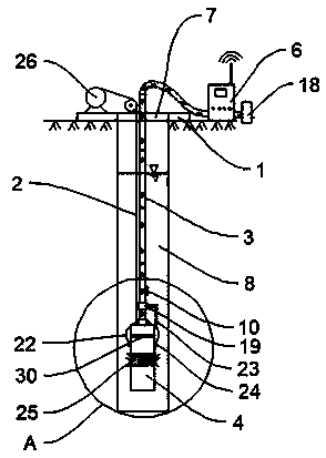
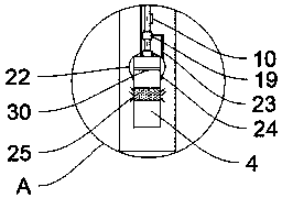
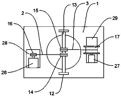
  • Intelligent water pumping experiment system
  • Intelligent water pumping experiment system
  • Intelligent water pumping experiment system

Examples


Embodiment 1

[0030] Such as Figure 1-Figure 5 As shown, the present embodiment provides an intelligent water pumping experiment system, including an installation substrate 1, a steel wire rope 2, a water pipe 3, a water pump 4, a liquid level gauge, a water pump cable 5, a liquid level gauge cable, and a control box 6. There are through holes 7, and the through holes 7 are facing the wellhead of the drilling well 8. The installation base plate 1 is provided with a lifting mechanism capable of controlling the synchronous lifting of the steel wire rope 2, water pipe 3, water pump cable 5 and liquid level gauge cable; the steel wire rope 2, water pipe 3 and water pump cable 5. One end extending into the well 8 through the through hole 7 is connected to the water pump 4 in the well 8, and the end of the liquid level gauge cable extending into the well 8 through the through hole 7 is connected to the liquid level gauge in the well 8. , the other end of the steel wire rope 2 is fixedly connecte...

Embodiment 2

[0034] This embodiment is optimized and defined on the basis of the above-mentioned embodiment 1.

[0035] Lifting mechanism comprises installation frame 12, steel wire rope rewinding device and water pipe rewinding device, and installation frame 12 is provided with connecting shaft 13, is connected with pulley one 14 and pulley two 15 in rotation on connecting shaft 13, and pulley one 14 and pulley two 15 are equal to each other. Located above the through hole 7, the wire rope winding device includes a wire rope winch 16 arranged on the installation base plate 1 for winding the wire rope 2. One end of the wire rope is fixedly connected to the wire rope winch, and the other end goes around the pulley 14 and is located in the drilling well 8. The water pump 4 is connected, and the water pipe winding device includes a water pipe winch 17 installed on the installation base plate 1 for winding the water pipe 3, the water pump cable 5 and the water level gauge cable 11. When the wat...

Embodiment 3

[0038] This embodiment is optimized and defined on the basis of the above-mentioned embodiment 2.

[0039] In order to facilitate the synchronous lifting operation of the water pump cable 5, the water level gauge cable 11 and the water pipe 3, the water pump cable 5 and the water level gauge cable 11 are all fixed on the outside of the water pipe 3 by binding.


PUM


Abstract

The invention belongs to the technical field of hydrogeology test equipment, and particularly relates to an intelligent water pumping experiment system. The system comprises an installation substrate,a steel wire rope, a water pipe, a water pump, a liquid level meter, a water pump cable, a liquid level meter cable and a control box, wherein the installation substrate is provided with a through hole which just faces the mouth of a drilling well; and the installation substrate is provided with a lifting mechanism capable of controlling the steel wire rope, the water pipe, the water pump cable and the liquid level meter cable to synchronously lift. The intelligent water pumping experiment system which adopts the technical scheme of the invention has the advantages of simple structure and lowconstruction cost and can truly realize the accurate automation control of an underground water level and flow, and meanwhile, the drawdown of a plurality of water levels can be realized. Compared with three hydrogeology parameters obtained by a traditional drawdown water pumping experiment, the system is rich and accurate.

Description

technical field [0001] The invention belongs to the technical field of hydrogeological experiment equipment, and in particular relates to an intelligent pumping experiment system. Background technique [0002] Hydrogeological parameters are important basic data for identifying groundwater occurrence status, water resource development evaluation, aquifer pollution risk assessment, and research on groundwater migration characteristics, while conducting groundwater drilling and pumping experiments is an important basis for identifying groundwater-related hydrogeological parameters. One of the means. At present, the groundwater drilling and pumping experiments are still mainly carried out manually. The water level in the well is regularly measured by using a multimeter and wires according to the time interval required by the specification. At the same time, the water meter or the water volume of the triangular weir is used to regularly measure the pumping flow. Manually recordin...

Claims


Application Information

Patent Timeline
Patent Type & Authority Applications(China)
IPC IPC(8): G01N33/24G05D27/02
CPCG01N33/24G05D27/02
Inventor 廖云平董平彭海游余瞻
Owner CHONGQING INST OF GEOLOGY & MINERAL RESOURCES
Learn More