Microwave plasma vapor phase epitaxy deposition equipment with lifting device

A microwave plasma and vapor phase epitaxy technology, applied in electrical components, gaseous chemical plating, coatings, etc., can solve the problems of microwave difficulties, limited cavity operation space, inconvenient maintenance of substrate equipment, etc., to reduce the probability of errors, Simple operation and improved operability

Pending Publication Date: 2022-03-29
广东众元半导体科技有限公司
View PDF9 Cites 0 Cited by
  • Summary
  • Abstract
  • Description
  • Claims
  • Application Information

AI Technical Summary

Problems solved by technology

This requires a multifunctional substrate stage, especially the substrate stage has functions such as rotation and up and down movement to enhance the uniformity of the material during the growth process, and this brings certain difficulties for feeding microwaves into the cavity from the bottom
However, when the microwave system enters the cavity from the top, due to the requirements on the sealing performance of the cavity, the operating space of the general cavity is very limited, which brings inconvenience to substrate placement or equipment maintenance

Method used


Image

  • Microwave plasma vapor phase epitaxy deposition equipment with lifting device

Examples


Embodiment 1

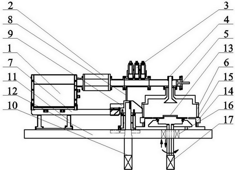
[0010] Embodiment 1: refer to figure 1 , a microwave plasma vapor phase epitaxy deposition equipment with a lifting device provided by the present invention is mainly composed of a microwave transmission system, an upper cavity 6, a transmission system support table connector 9, a lifting push rod and a motor 10, and a working platform 12. The lower cavity 14 and the substrate stage 13 are composed, wherein the microwave transmission system is composed of a microwave source 1, a coupler 2, a three-axis matcher 3, a mode converter 4 and a short circuit 5, which are sequentially fixedly connected, wherein the microwave is transmitted through the microwave The system is coupled from the top of the upper chamber 6 into the working chamber composed of the upper chamber 6 and the lower chamber 14. The microwave transmission system is fixedly connected to the upper chamber 6 through the mode converter 4. The transmission system under the three-axis matcher 3 The support platform conn...

Embodiment 2

[0011] Embodiment 2: refer to figure 1 , on the basis of Embodiment 1, the microwave source support table 7 and the working platform 12 are connected by a gas spring 11 to play a balancing role in motion buffering. The gas spring 11 can also be a cylinder or an electric screw rod or other active driving mechanism , to balance the difference in the left and right lever forces of the movement.

Embodiment 3

[0012] Embodiment 3: refer to figure 1 , on the basis of Embodiment 1, the upper chamber 6 and the lower chamber 14 are provided with a sealing ring 15, when the upper chamber falls, the lifting push rod and the motor 10 apply the contact pressure between the upper and lower chambers through the reverse rotation of the motor , to achieve enhanced sealing performance.


PUM

PropertyMeasurementUnit
diameteraaaaaaaaaa

Abstract

The invention discloses microwave plasma vapor phase epitaxy deposition equipment with a lifting device. The microwave plasma vapor phase epitaxy deposition equipment mainly comprises a microwave transmission system, an upper cavity, a microwave source supporting table, a transmission system supporting table connecting piece, a lifting push rod, a motor, a working platform, a substrate table, a lower cavity, a sealing ring, magnetic fluid, a substrate table push rod and a motor. According to the invention, the microwave transmission system and the upper cavity part of the microwave plasma vapor phase epitaxy deposition equipment are modularly designed, so that integral lifting can be realized in the substrate placement and equipment maintenance processes, and the modular design can ensure sufficient operation space in the substrate placement process; the direct influence of the substrate table structure on microwave transmission is reduced, and meanwhile, new hidden trouble caused by complex operation in the process of equipment maintenance and the like is avoided.

Description

technical field [0001] The invention relates to the technical field of chemical vapor deposition, in particular to a microwave plasma vapor phase epitaxy deposition equipment with a lifting device. Background technique [0002] Diamond is called the ultimate semiconductor, and diamond growth through microwave plasma vapor phase epitaxy deposition equipment is by far the purest and most efficient way. Its working principle is that the cylindrical cavity and the microwave resonate to generate a central strong electric field to ionize the hydrogen in the cavity, make it into a plasma, and then pass in methane and ionize it into carbon-containing groups to deposit on the diamond substrate for diamond growth. . Due to the characteristics of the cavity itself, the plasma density distribution gradient in the excited plasma sphere is significant. This requires a multifunctional substrate stage, especially the substrate stage has functions such as rotation and up and down movement ...

Claims


Application Information

Patent Timeline
Patent Type & Authority Applications(China)
IPC IPC(8): C23C16/27C23C16/458C23C16/511H01J37/32
CPCC23C16/274C23C16/511C23C16/4581H01J37/32
Inventor 刘胜甘志银
Owner 广东众元半导体科技有限公司
Why Eureka
Try Eureka