Intelligent pumping experiment system
A water pumping experiment, intelligent technology, applied in the direction of control/regulation system, material inspection product, and simultaneous control of multiple variables, etc., can solve the problems of inability to realize automatic control, failure to successfully complete the pumping experiment, and unstable voltage, etc., to reduce the water pump Improve the risk of difficulty, rich and accurate hydrogeological parameters, and avoid the troublesome effect of manual operation
- Summary
- Abstract
- Description
- Claims
- Application Information
AI Technical Summary
Problems solved by technology
Method used
Image
Examples
Embodiment 1
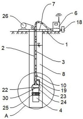
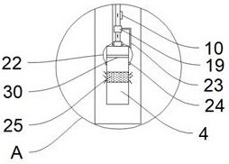
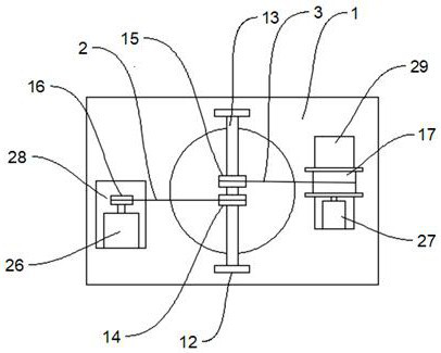
[0030] like Figure 1-Figure 5 As shown, the present embodiment provides an intelligent water pumping experiment system, including an installation substrate 1, a steel wire rope 2, a water pipe 3, a water pump 4, a liquid level gauge, a water pump cable 5, a liquid level gauge cable, and a control box 6. There are through holes 7, and the through holes 7 are facing the wellhead of the drilling well 8. The installation base plate 1 is provided with a lifting mechanism capable of controlling the synchronous lifting of the steel wire rope 2, water pipe 3, water pump cable 5 and liquid level gauge cable; the steel wire rope 2, water pipe 3 and water pump cable 5. One end extending into the well 8 through the through hole 7 is connected to the water pump 4 in the well 8, and the end of the liquid level gauge cable extending into the well 8 through the through hole 7 is connected to the liquid level gauge in the well 8. , the other end of the steel wire rope 2 is fixedly connected t...
Embodiment 2
[0034] This embodiment is optimized and defined on the basis of the above-mentioned embodiment 1.
[0035] Lifting mechanism comprises installation frame 12, steel wire rope rewinding device and water pipe rewinding device, and installation frame 12 is provided with connecting shaft 13, is connected with pulley one 14 and pulley two 15 in rotation on connecting shaft 13, and pulley one 14 and pulley two 15 are equal to each other. Located above the through hole 7, the wire rope winding device includes a wire rope winch 16 arranged on the installation base plate 1 for winding the wire rope 2. One end of the wire rope is fixedly connected to the wire rope winch, and the other end goes around the pulley 14 and is located in the drilling well 8. The water pump 4 is connected, and the water pipe winding device includes a water pipe winch 17 installed on the installation base plate 1 for winding the water pipe 3, the water pump cable 5 and the water level gauge cable 11. When the wat...
Embodiment 3
[0038] This embodiment is optimized and defined on the basis of the above-mentioned embodiment 2.
[0039] In order to facilitate the synchronous lifting operation of the water pump cable 5, the water level gauge cable 11 and the water pipe 3, the water pump cable 5 and the water level gauge cable 11 are all fixed on the outside of the water pipe 3 by binding.
PUM
 Abstract
Description
Claims
Application Information
 - R&D
- Intellectual Property
- Life Sciences
- Materials
- Tech Scout
- Unparalleled Data Quality
- Higher Quality Content
- 60% Fewer Hallucinations
Browse by: Latest US Patents, China's latest patents, Technical Efficacy Thesaurus, Application Domain, Technology Topic, Popular Technical Reports.
© 2025 PatSnap. All rights reserved.Legal|Privacy policy|Modern Slavery Act Transparency Statement|Sitemap|About US| Contact US: help@patsnap.com


