Cross-linked film blow molding device

A technology of blow molding device and mounting frame, which is applied in the direction of transportation and packaging, other household utensils, winding strips, etc., which can solve the problems of inconvenient film inflation operation and inconvenient film automatic traction, so as to improve the uniformity of blowing degree of effect

Active Publication Date: 2022-06-07
郭必威
View PDF12 Cites 0 Cited by
  • Summary
  • Abstract
  • Description
  • Claims
  • Application Information

AI Technical Summary

Problems solved by technology

[0005] The purpose of the present invention is to provide a cross-linked film blowing device to solve the above-mentioned background technology. The existing cross-linked film blowing device is inconvenient to perform uniform blowing operation on the film, and at the same time it is inconvenient to carry out automatic traction of the film. The problem

Method used


Image

  • Cross-linked film blow molding device
  • Cross-linked film blow molding device
  • Cross-linked film blow molding device

Examples


Embodiment 1

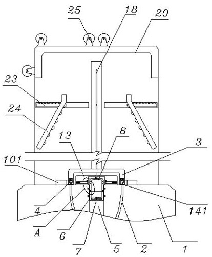
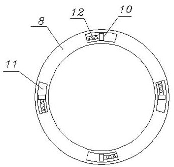
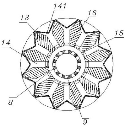
[0035] see Figure 1-5 , including the head 1, the head 1 is connected with the extruder at the bottom, and there is a blow molding channel 2 in the head 1, and a setting frame 3 is placed above the head 1, and a fan is installed on the head 1. Ring 101, the bottom of the shaping frame 3 is provided with a shaping channel 4, and the shaping channel 4 is located above the blowing channel 2, and the shaping frame 3 is filled with cooling water; The center position, and the bearing on the inner wall of the middle part of the gas transmission channel 5 is provided with a guide cylinder 6, and the bottom of the guide cylinder 6 is fixed with an impeller 7, a blowing cylinder 8 is installed above the guide cylinder 6, and the top edge of the blowing cylinder 8 is opened. There is a blowing hole 9, and the top of the blowing cylinder 8 is located above the handpiece 1, the top of the handpiece 1 is fixed with an air-guiding ring seat 13, and the air-guiding ring seat 13 is located be...

Embodiment 2

[0037] see figure 1 and Figure 6-8 , the screw 18, the screw 18 is installed on the top of the blowing cylinder 8, and the screw 18 is threadedly sleeved with a setting frame 3, the front and rear sides of the setting frame 3 are fixed with a limit rack 19, and one end of the limit rack 19 is The side wall of the mounting frame 20 is embedded and slidably installed, and the mounting frame 20 is fixed on the top of the machine head 1. The main gear 21 and the auxiliary gear 22 are mounted on the embedded bearing inside the mounting frame 20, and the main gear 21 and the auxiliary gear 22 are installed. They are connected by a synchronous belt, a movable rack 23 is meshed below the auxiliary gear 22, and the movable rack 23 is embedded in the mounting frame 20 and slides laterally, and one end of the movable rack 23 is fixed with a splint 24. The splint 24 is located at the inner position of the mounting frame 20, and the chevron splint 24 is located at the two sides of the se...


PUM


Abstract

The invention discloses a cross-linked film blow molding device which comprises a machine head, the machine head is connected with an extruder at the bottom, a shaping channel is formed in the bottom of a shaping frame, the cross-linked film blow molding device further comprises an air conveying channel, the air conveying channel is formed in the center of the machine head in a penetrating mode, and an air blowing cylinder is installed above a guide cylinder; the top of the machine head is fixedly provided with an air guide ring seat, and the top of the sealing plate is connected with a tooth roller; the screw rod is installed at the top of the air blowing cylinder, the screw rod is sleeved with a shaping frame in a threaded mode, limiting racks are fixed to the front side and the rear side of the shaping frame correspondingly, a main gear and an auxiliary gear are installed in an embedded bearing in the installation frame, and a movable rack is arranged below the auxiliary gear in an engaged mode; the herringbone clamping plate is located in the mounting frame. According to the blow molding device for the cross-linked film, the film is uniformly blown up, the film is prevented from being deformed, meanwhile, automatic traction can be carried out, and troubles caused by manual traction are avoided.

Description

technical field [0001] The invention relates to the technical field of cross-linked film blowing, in particular to a cross-linked film blowing device. Background technique [0002] The blow molding of the cross-linked film is to extrude and melt the material through the extruder, and then export it from the blow molding channel in the machine head and inflate it through the internal high-speed air flow, cooperate with the cooling and forming of the external phoenix ring, and then pass through the blow molding. The splint is used for shrinking and guiding and subsequent winding of the formed film, but the existing cross-linked film blowing device has the following problems in use: [0003] During the molding process of the film, the inner diameter is much larger than the outer diameter of the high-speed compressed air blown out from the middle, resulting in uneven force on the film during the inflation of the compressed air mass, which is prone to deformation, and it is incon...

Claims


Application Information

Patent Timeline
Patent Type & Authority Applications(China)
IPC IPC(8): B29C55/28B29C35/16B29C37/00B65H20/14B65H23/032B29L7/00
CPCB29C55/28B29C35/16B29C37/00B65H20/14B65H23/0322B65H2701/1133B65H2701/175B29L2007/00Y02P70/10
Inventor 郭必威
Owner 郭必威
Why Eureka
Try Eureka