
Display control method and device for terminal equipment

A display control method and technology of terminal equipment, which are applied in image communication, electrical components, stereo systems, etc., to achieve the effects of improving user experience, better 3D viewing effect, and simple method.

Active Publication Date: 2016-03-02
SPREADTRUM COMM (SHANGHAI) CO LTD
View PDF12 Cites 0 Cited by
  • Summary
  • Abstract
  • Description
  • Claims
  • Application Information

AI Technical Summary

Problems solved by technology

There is no corresponding solution in the prior art to realize the 3D interface display with any viewing angle conversion according to the observer's observation position and angle.

Method used


Image

  • Display control method and device for terminal equipment
  • Display control method and device for terminal equipment
  • Display control method and device for terminal equipment

Examples


Embodiment 1

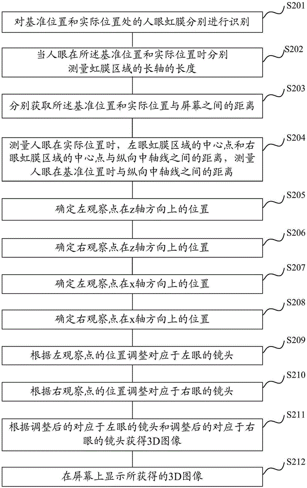
[0078] In this embodiment, the implementation process of determining the spatial position of the observation point based on the actual position of the human eyes, and then updating the 3D image displayed on the screen of the terminal device based on the spatial position of the observation point is mainly described.

[0079] figure 2 It is a schematic flowchart of a display control method for a terminal device provided in Embodiment 1 of the present invention.

[0080] First, step S201 is executed to identify the iris of the human eye at the reference position and the actual position respectively.

[0081] In this embodiment, description is made by taking the terminal device as a mobile phone as an example. The mobile phone contains a front-facing camera, and the front-facing camera is located in the center above the screen of the mobile phone. The reference position is that the observer is facing the screen of the mobile phone and the distance between the observer's eyes an...

Embodiment 2

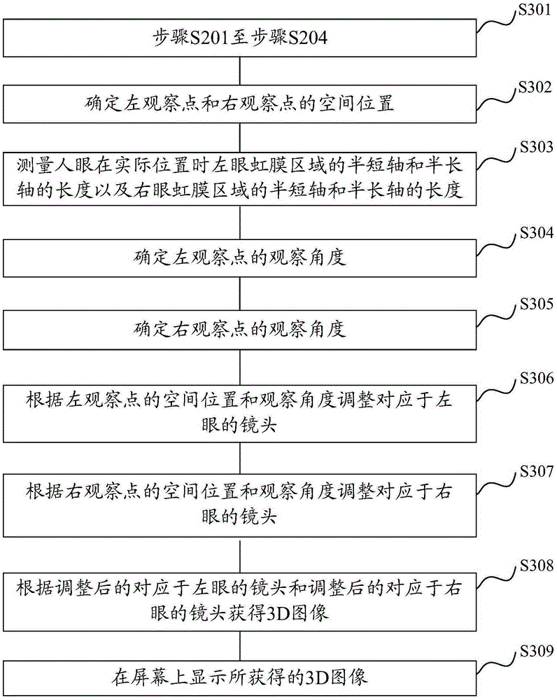
[0114] In this embodiment, the realization of determining the spatial position and observation angle of the observation point based on the actual position of the human eyes, and then updating the 3D image displayed on the screen of the terminal device based on the spatial position and observation angle of the observation point The process is explained.

[0115] image 3 It is a schematic flowchart of a display control method for a terminal device provided in Embodiment 2 of the present invention.

[0116] Such as image 3 As shown, step 301 is first executed, and step 301 corresponds to figure 1 Steps S201 to S204 in , mainly through the recognition of the iris of the human eye at the reference position and the actual position, respectively, to obtain some measured values ​​and calculated values ​​used to determine the spatial position of the observation point. For details, please refer to Step S201 to step S204.

[0117] Step S302 is executed to determine the spatial posi...


PUM


Abstract

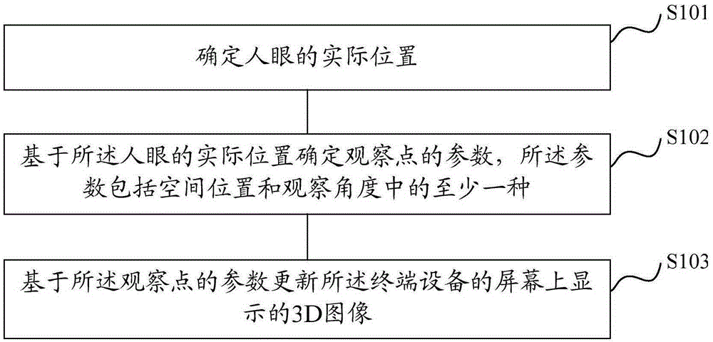
A display control method and device for a terminal device, the method comprising: determining the actual position of the human eye; determining a parameter of an observation point based on the actual position of the human eye, the parameter including at least one of a spatial position and an observation angle Type: updating the 3D image displayed on the screen of the terminal device based on the parameter of the observation point. The technical solution of the present invention realizes the 3D interface display of arbitrary viewing angle conversion.

Description

technical field [0001] The present invention relates to the technical field of image display, in particular to a display control method and device for terminal equipment. Background technique [0002] With the development of three-dimensional (3D) image display technology, various 3D terminal devices such as 3D TV, 3D tablet, and 3D mobile phone have appeared in the market. The 3D terminal device displays 3D images based on naked-eye 3D display technology. [0003] When human eyes look at objects, the images formed by the two eyes on the retina are not exactly the same. The left eye sees more of the left side of the object, and the right eye sees more of the right side of the object. After the images are synthesized by the brain, the three-dimensional vision of objects can be produced. Glasses-free 3D display technology uses this principle to present stereoscopic images. Glasses-free 3D display technology mainly combines two images from different angles suitable for left a...

Claims


Application Information

Patent Timeline
Patent Type & Authority Patents(China)
IPC IPC(8): H04N13/00H04N13/02
Inventor 夏璐王佳佳
Owner SPREADTRUM COMM (SHANGHAI) CO LTD
Learn More