Display control method and device for terminal equipment
A display control method and terminal equipment technology, applied in image communication, electrical components, stereoscopic systems, etc., to achieve the effect of improving user experience and better 3D viewing effect
- Summary
- Abstract
- Description
- Claims
- Application Information
AI Technical Summary
Problems solved by technology
Method used
Image
Examples
Embodiment 1
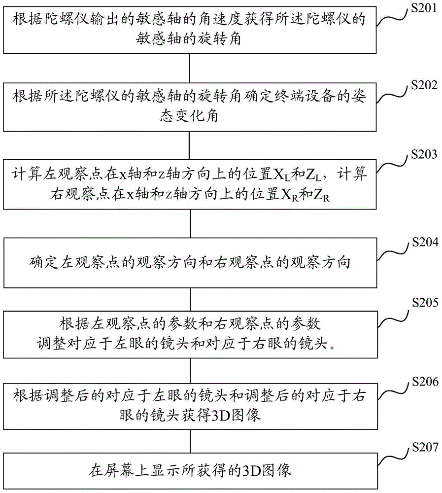
[0079] In this embodiment, the posture of the terminal device is determined by the gyroscope, the spatial position of the observation point is determined by the posture of the terminal device, and the 3D image displayed on the screen of the terminal device is updated based on the spatial position of the observation point The implementation process is described.
[0080] figure 2 It is a schematic flowchart of a display control method for a terminal device provided in Embodiment 1 of the present invention.
[0081] First, step S201 is executed to obtain the rotation angle of the sensitive axis of the gyroscope according to the angular velocity of the sensitive axis output by the gyroscope.
[0082] The sensitive axis of the gyroscope corresponds to the direction of the coordinate axis in the space xyz coordinate system described in step S101. For example, if the terminal device includes three single-axis gyroscopes, when the screen of the terminal device is facing the human ...
Embodiment 2
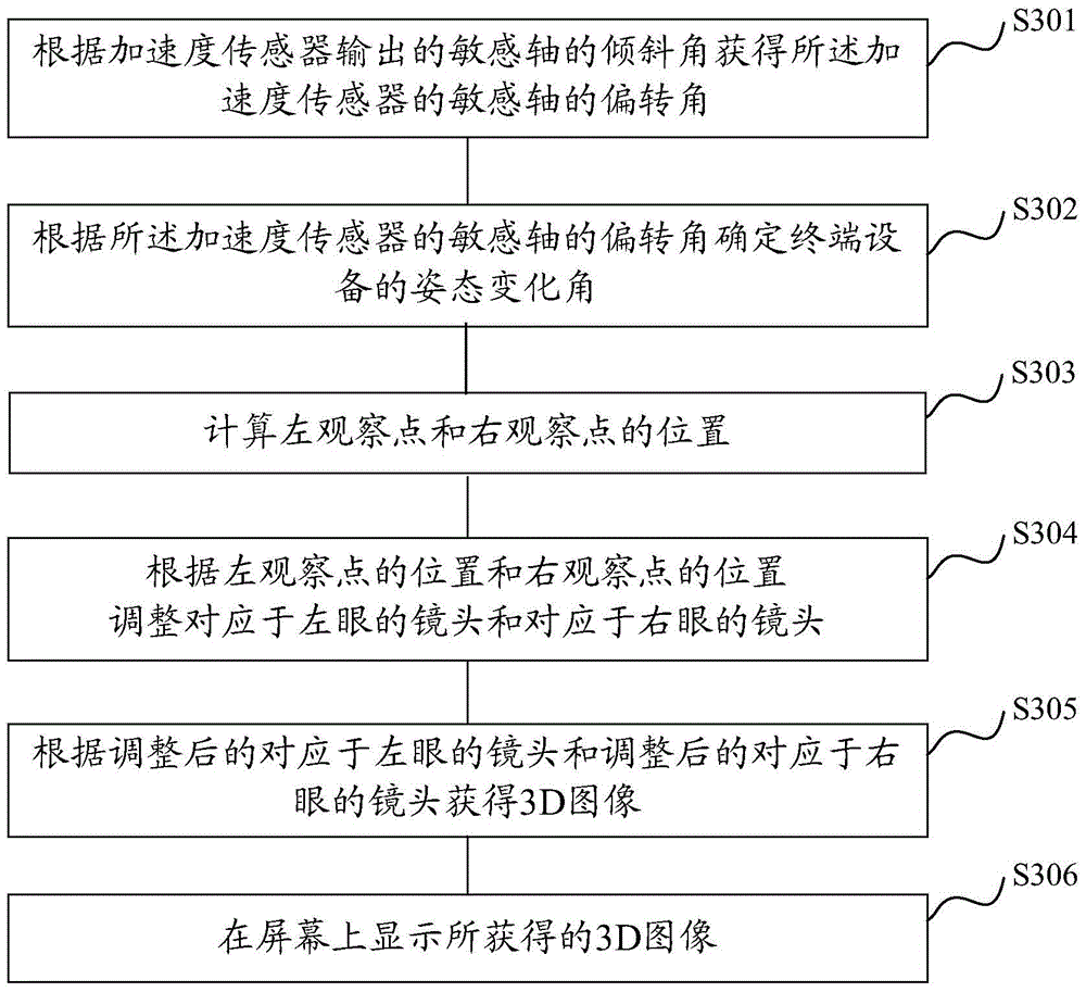
[0125] In this embodiment, the posture of the terminal device is determined by the acceleration sensor, the spatial position of the observation point is determined by the posture of the terminal device, and the 3D image displayed on the screen of the terminal device is updated based on the spatial position of the observation point The implementation process is described.
[0126] image 3 It is a schematic flowchart of a display control method for a terminal device provided in Embodiment 2 of the present invention.
[0127] First, step S301 is executed to obtain the deflection angle of the sensitive axis of the acceleration sensor according to the inclination angle of the sensitive axis output by the acceleration sensor.
[0128] The sensitive axis of the acceleration sensor corresponds to the direction of the coordinate axis in the spatial xyz coordinate system described in step S101. For example, if the terminal device includes a three-axis acceleration sensor, the three s...
PUM
 Abstract
Description
Claims
Application Information
 - R&D
- Intellectual Property
- Life Sciences
- Materials
- Tech Scout
- Unparalleled Data Quality
- Higher Quality Content
- 60% Fewer Hallucinations
Browse by: Latest US Patents, China's latest patents, Technical Efficacy Thesaurus, Application Domain, Technology Topic, Popular Technical Reports.
© 2025 PatSnap. All rights reserved.Legal|Privacy policy|Modern Slavery Act Transparency Statement|Sitemap|About US| Contact US: help@patsnap.com


