Heat shield assembly

A heat shielding and heat shielding technology, applied in lighting and heating equipment, combustion methods, combustion chambers, etc., can solve the problem of oxide skin on metal brackets, and achieve the effect of cooling components well, avoiding damage and saving cooling air.

Inactive Publication Date: 2014-01-15
SIEMENS AG
View PDF7 Cites 7 Cited by
  • Summary
  • Abstract
  • Description
  • Claims
  • Application Information

AI Technical Summary

Problems solved by technology

If the cooling is not sufficient, scaling of the metal support can occur

Method used


Image

  • Heat shield assembly

Examples


Embodiment Construction

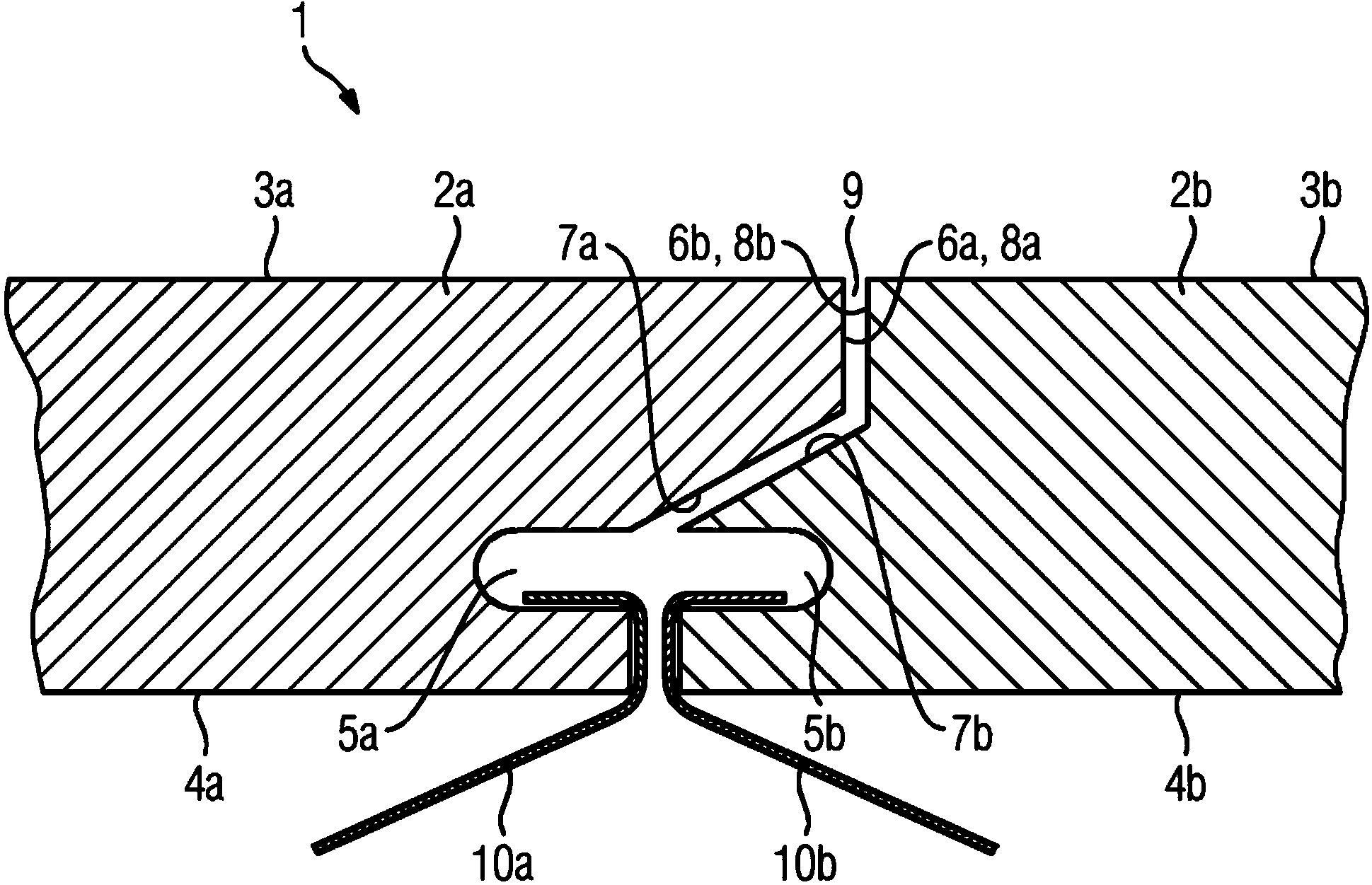
[0014] figure 1 A heat shield 1 according to the invention is shown which has two adjoining heat shields 2a, 2b. In this case, the first heat shield 2a has a hot gas side 3a and a cold gas side 4a. The second heat shield 2b likewise comprises a hot gas side 3b and a cold gas side 4b. The direction from the hot gas side 3a to the cold gas side 4a is called radial direction. The heat shield 2a, 2b comprises at least two side walls 6a, 6b adjoining each other. The first heat shield 2a now has engagement recesses 5a at a distance from the cold air side 4a and the hot air side 3a. Engagement groove 5 a can here be regarded as a groove that does not extend over the entire axial length of side wall 6 a , wherein the axial direction of side wall 6 a is perpendicular to the radial direction. The second heat shield 2b likewise has the same engagement recess 5b. The brackets 10 a , 10 b are now engaged by means of clamping arms from the cold air side 4 a , 4 b into the engagement gr...


PUM


Abstract

The invention relates a heat shield assembly (1), comprising at least two neighboring heat shields (2a, 2b), said shields being a first heat shield (2a) and a second heat shield (2b), each having a hot gas side (3a, 3b) and an opposing cold gas side (4a, 4b), wherein the heat shields (2a, 2b) have a neighboring side wall (6a, 6b) that connects the hot gas side (3a, 3b) and the cold gas side (4a, 4b), wherein a respective engagement pocket (5a, 5b), which is spaced from the hot gas side (3a, 3b) and the cold gas side (4a, 4b), is provided in the respective neighboring side wall (6a, 6b), wherein adjacent heat shields (2a, 2b) overlap one another and the one side wall (6a) of the first heat shield (3a) has a protrusion extending from the engagement pocket (5a) in the direction of the hot gas side (3a), wherein the protrusion has at least one protrusion side (7a); and a protrusion front edge (8a) connecting thereto, and wherein the second heat shield (2b) has a cutout that is essentially complementary to the protrusion and extending from the engagement pocket (5b) in the direction of the hot gas side (3b), wherein the cutout has at least one cutout side (7b) and a cutout rear edge (8b) connecting thereto, which are arranged such that, extending from the engagement pocket (5a, 5b), a gap (9) that is open toward the hot gas side (3a, 3b) is formed between the cutout and the protrusion, and wherein both the protrusion side (7a) and the cutout side (7b) have a gradient relative to the respective cold gas side (4a, 4b).

Description

technical field [0001] The invention relates to a heat shield having at least two adjoining heat shields, namely a first heat shield and a second heat shield, each having a hot gas side and an opposite cold gas side, wherein the heat shields The screen has adjacent side walls connecting the hot gas side and the cold gas side, and at the same time, in the adjacent side walls, an embedding groove spaced apart from the hot gas side and the cold gas side is opened respectively. Background technique [0002] The walls of high-temperature reactors, such as those used in combustion chambers of gas turbines operating under pressure, must be protected against high-temperature loads, such as hot gases, by means of suitable insulation screens in their supporting structure. In this regard, we can provide not only metal materials but also ceramic materials that are characterized by high heat resistance, corrosion resistance, and low thermal conductivity. [0003] One such heat shield is...

Claims


Application Information

Patent Timeline
Patent Type & Authority Applications(China)
IPC IPC(8): F23M5/02F23M5/08F23R3/00
CPCF23M5/02F23M5/085F23M2700/0053F23M2900/05005F23R3/007
Inventor A.伯特彻S.格伦德尔A.克鲁格
Owner SIEMENS AG
Why Eureka
Try Eureka