Synchronization mouth mirror

A technology of oral mirror and lens, applied in the direction of oral mirror, endoscope, medical science, etc., can solve the problems of difficult observation by human eyes, time-consuming and laborious, inconvenient operation, etc., and achieves favorable observation, convenient operation and good lighting effect. Effect

Inactive Publication Date: 2014-01-22
NANJING QINHUAI HOSPITAL
View PDF1 Cites 7 Cited by
  • Summary
  • Abstract
  • Description
  • Claims
  • Application Information

AI Technical Summary

Problems solved by technology

[0002] With the progress of mankind, the development of society, people's constant attention to the medical cause, and the continuous updating of medical equipment, some traditional medical equipment obviously cannot keep up with the development of the times. It is inevitable to use oral mirrors in oral diagnosis. Traditional Dental mirrors are only composed of a lens and a handle, and all of them are artificially observed. Because the human oral environment is limited and the human eye is not easy to observe, there are many oral diseases that cannot be diagnosed in detail. However, with scientific With the development of technology, people began to apply other technologies to medical equipment, such as a synchronous display dental mirror with application number 201220207882.7, which added LED lights and a camera to its lens, and the camera transmits images to the computer through the USB interface. Therefore, people can observe the inside of the oral cavity very conveniently, but the synchronous display oral mirror is inconvenient to operate because the design structure is too simple, and the internal space of the oral cavity is limited, so it is obviously not convenient to use a straight handle to operate inside the oral cavity. Although the camera is used to observe the interior of the oral cavity, sometimes the dentist still has to observe the internal environment of the oral cavity with the naked eye. At this time, he needs to use other tools, which is time-consuming and laborious. Change, the requirements for the direction of the light are also different

Method used


Image

  • Synchronization mouth mirror
  • Synchronization mouth mirror

Examples


Embodiment Construction

[0012] specific implementation plan

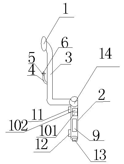
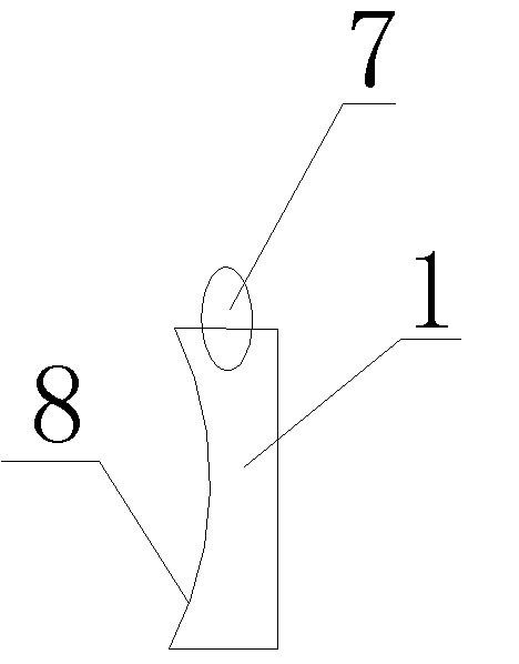
[0013] Such as figure 1 figure 2 As shown, a synchronous dental mirror includes a lens 1 and a handle 2, an L-shaped connecting section 3 is arranged between the handle 2 and the lens 1, and a guide rod 4 is provided on the connecting section 3, and the length of the guide rod 4 is It is 80mm-100mm, and what the present invention adopts is 90mm. A light frame 5 is connected to the guide rod 4, a spotlight 6 is arranged in the light frame 5, the lens 1 includes a camera 7 and a mirror 8, the camera 7 is located at the front end of the lens 1, and the handle 2 is Hollow structure, the inside of the handle 2 is provided with batteries 9, 101, image sensing module and image processing module 102, the outside of the handle 2 is provided with a camera switch 11 and a spotlight switch 12, and the tail of the handle 2 is provided with a USB interface 13 , this oral mirror has a reasonable design structure, practical functions, and is easy to o...


PUM

PropertyMeasurementUnit
Lengthaaaaaaaaaa

Abstract

The invention discloses a synchronization mouth mirror, and relates to the field of medical equipment. The synchronization mouth mirror comprises a lens and a handle. An L-shaped connecting section is arranged between the handle and the lens. A guide rod is arranged on the connecting section and 80mm-100mm in length. A lamp rack is connected to the guide rod. A spot lamp is arranged in the lamp rack. The lens comprises a camera and a lens surface. The camera is located at the forefront of the lens. The handle is of a hollow structure. A battery, an image sensing module and an image processing module are arranged inside the handle. A camera switch and a spot lamp switch are arranged outside the handle. A USB interface is formed in the tail of the handle. The synchronization mouth mirror is reasonable in design and structure, practical in functions and convenient to operate. A doctor can synchronously observe the interior of the mouth, can observe the interior of the mouth with naked eyes without using other tools, and can make specific and detailed diagnosis when examining the interior of the mouth of a patient.

Description

technical field [0001] The invention relates to a synchronous dental mirror and relates to the field of medical equipment. Background technique [0002] With the progress of mankind, the development of society, people's constant attention to the medical cause, and the continuous updating of medical equipment, some traditional medical equipment obviously cannot keep up with the development of the times. It is inevitable to use oral mirrors in oral diagnosis. Traditional Dental mirrors are only composed of a lens and a handle, and all of them are artificially observed. Because the human oral environment is limited and the human eye is not easy to observe, there are many oral diseases that cannot be diagnosed in detail. However, with scientific With the development of technology, people began to apply other technologies to medical equipment, such as a synchronous display dental mirror with application number 201220207882.7, which added LED lights and a camera to its lens, a...

Claims


Application Information

Patent Timeline
IPC IPC(8): A61B1/247A61B1/06A61B1/04
Inventor 宋正权
Owner NANJING QINHUAI HOSPITAL
Why Eureka
Try Eureka