
Deburring device

A deburring and equipment technology, applied in metal processing equipment, grinding/polishing equipment, grinding machines, etc., can solve problems such as difficulty in removing burrs, bruised processing surfaces, waste of labor, etc., to reduce cleaning workload and efficiency. The effect of improving and reducing labor intensity

Inactive Publication Date: 2014-01-22
YANGZHOU RONGTAI IND DEV
View PDF0 Cites 3 Cited by
  • Summary
  • Abstract
  • Description
  • Claims
  • Application Information

AI Technical Summary

Problems solved by technology

However, for some special parts, especially parts with holes, it is very difficult to manually remove the burrs in the holes, and at the same time, there are problems such as waste of labor, leakage, and damage to the processing surface.

Method used


Image

  • Deburring device
  • Deburring device

Examples


Embodiment Construction

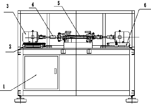
[0013] In the present invention, an electrical cabinet 1 is arranged at the lower part of the frame to control the operation of the motor 3. The motor 3 is arranged on the track 2 through the track connecting groove 6, and can move back and forth along the track 2; therefore, it can drive the hole brush 4 connected to it to move back and forth , and the hole brush 4 can be driven by the motor 3 to rotate, thereby forming a spiral motion curve to remove the burr in the hole of the workpiece.

[0014] The workpiece 5 of the present invention is fixed by a clamp, and its height is adjustable up and down, so that it corresponds to the position of the hole brush 4 .

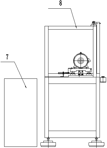
[0015] The present invention is equipped with a dust suction device 7, and at the same time that the equipment removes burrs, the dust suction device 7 is turned on to suck away the burrs in time, preventing the accumulation of burrs from affecting the neatness of the equipment, or blocking the work of the hole brush 4...


PUM


Abstract

The invention relates to a deburring device. The deburring device comprises a rack, a fixture used for clamping a workpiece is arranged on the rack, and hole brushes are arranged at two ends of the workpiece, driven by a power unit to rotate and can do front and back motion in the horizontal direction. The deburring device has the advantages that the rotatable hole brushes driven by the drive unit can move into the workpiece and achieve rotating motion relative to the workpiece, burrs can be removed quickly and efficiently by means of the friction formed between the hole brushes and the inner wall of a hole of the workpiece; the deburring device is further provided with a dust sucking device, the dust sucking device can suck out the burrs which are cleaned out timely to keep the whole device clean and the workpiece will not be abraded by the burrs cleaned out; in addition, the follow-up cleaning workload is reduced, the labor intensity of operators is relieved, and the continuity of removing and cleaning is truly achieved.

Description

technical field [0001] The invention relates to a deburring device and relates to the technical field of mechanical processing. Background technique [0002] After aluminum products are machined, there are often burrs and flanging at the joints of the processing. This flanging burr will fall off in the parts during operation or installation and use, which will seriously affect the mechanical and safety performance of the equipment. To ensure that this does not happen, this burr must be removed in its entirety. However, for some special parts, especially parts with holes, it is very difficult to manually remove the burrs in the holes, and at the same time, problems such as waste of labor, leakage, and bruising of the processed surface occur. For example, the burrs on the connecting parts after the internal processing of the automobile steering gear housing are manually repaired as described above. Contents of the invention [0003] In view of the above defects, the prese...

Claims


Application Information

Patent Timeline
Patent Type & Authority Applications(China)
IPC IPC(8): B24B9/04
CPCB24B9/04
Inventor 勾建勇崔美卿陈占胜
Owner YANGZHOU RONGTAI IND DEV
Learn More