A Two-way Constant Force Pneumatic Output Device Not Affected by Low Pressure

An output device, low pressure technology, applied in the direction of fluid pressure actuating device, etc., can solve the problems of difficult control of small constant force, inaccurate sensor measurement, and difficulty in keeping the output force value constant, so as to achieve the realization of small constant force output and air supply. Simple method, stable effect of gas film formation

Inactive Publication Date: 2015-10-28
沃孚尔传动技术(佛山)有限公司
View PDF6 Cites 0 Cited by
  • Summary
  • Abstract
  • Description
  • Claims
  • Application Information

AI Technical Summary

Problems solved by technology

[0004] In view of the problems in the existing constant force output device that the output force value is difficult to keep constant, the sensor measurement is not accurate enough, and the small constant force is difficult to control, the present invention provides a device that can realize two-way control, is not affected by tracheal disturbance, and has an accurate and stable output force value. A two-way constant force pneumatic output device with good performance

Method used


Image

  • A Two-way Constant Force Pneumatic Output Device Not Affected by Low Pressure
  • A Two-way Constant Force Pneumatic Output Device Not Affected by Low Pressure
  • A Two-way Constant Force Pneumatic Output Device Not Affected by Low Pressure

Examples


Embodiment Construction

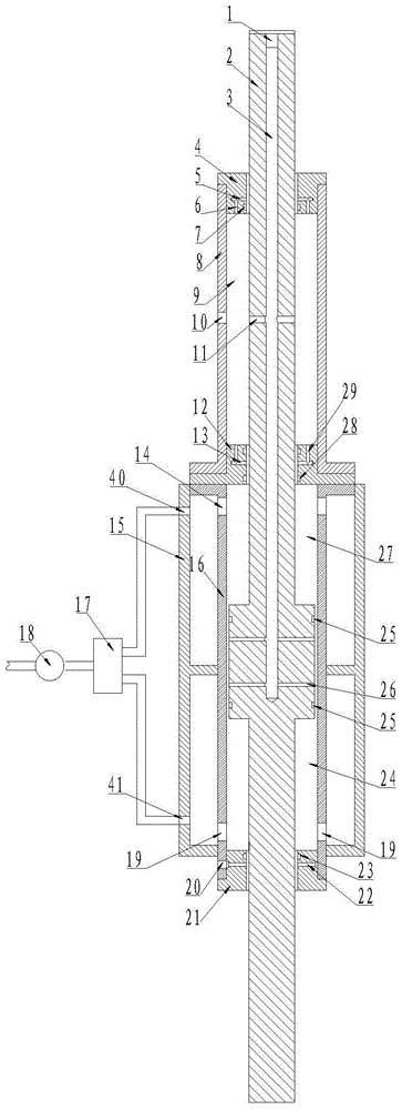
[0029] combined with Figure 1~5 , a two-way constant force pneumatic output device not affected by low pressure, including a connecting rod piston 2, a cylinder 16, an air storage sleeve, and an air bearing sleeve; the air bearing sleeve includes a first air bearing sleeve 12, a second air bearing sleeve 4 And the third air bearing cover 21, the air storage cover includes the first air storage cover 8 and the second air storage cover 15.

[0030] The first air bearing sleeve 12 is set in the first air storage sleeve 8, the first air storage sleeve 8 is fixedly connected to the end face of the cylinder barrel 16, the second air bearing sleeve 4 is sleeved on the upper end of the first air storage sleeve 8, and the third air storage sleeve 4 is sleeved on the upper end of the first air storage sleeve 8. The floating sleeve 21 is set on the lower end of the cylinder barrel 16 , and the second air storage sleeve 15 is set on the outside of the cylinder barrel 16 .

[0031] The c...


PUM


Abstract

The invention provides a bidirectional constant force pneumatic output device not affected by low pressure. The bidirectional constant force pneumatic output device not affected by low pressure comprises a connecting rod piston, a cylinder barrel, air storage sleeves and air flotation sleeves. The air flotation sleeves comprise a first air flotation sleeve, a second air flotation sleeve and a third air flotation sleeve, the air storage sleeves comprise a first air storage sleeve and a second air storage sleeve, the first air flotation sleeve is arranged in the first air storage sleeve in a sleeved mode, the first air storage sleeve is fixedly connected with an end surface of the cylinder barrel, the second air flotation sleeve is arranged at the upper end of the first air storage sleeve in a sleeved mode, the third air flotation sleeve is arranged at the lower end of the cylinder barrel, and the second air storage sleeve is arranged outside the cylinder barrel in a sleeved mode. The connecting rod piston is composed of a long rod, a short rod and a middle piston, wherein the middle piston is arranged in the cylinder barrel in a sleeved mode, a small interval is reserved between the wall of the middle piston and the cylinder barrel, the long rod penetrates through the first air flotation sleeve and the second air flotation sleeve, and the short rod end penetrates through the third air flotation sleeve. The bidirectional constant force pneumatic output device can achieve constant force output, is not affected by disturbance of an air pipe, is more stable in air film generation and is high in control accuracy.

Description

technical field [0001] The invention relates to a constant force output device. Background technique [0002] According to different application environments and application requirements, there are various structures and implementation methods for constant force output. Dynamic constant force output refers to loading a constant force value on a dynamically moving target workpiece. [0003] Hanging the target workpiece through weights is the simplest and most commonly used method of applying constant force. Since the mass of the weight is constant, the force acting on the target workpiece remains unchanged, but when the target workpiece is accelerating or decelerating, the weight The weight will generate an additional force acting on the target workpiece due to the influence of its own inertial force, and the greater the mass of the weight, the greater the effect, so this method is only suitable for low-speed or uniform-speed movement of the target workpiece. Torque motors,...

Claims


Application Information

Patent Timeline
Patent Type & Authority Patents(China)
IPC IPC(8): F15B15/14
Inventor 郑欣荣袁巧玲
Owner 沃孚尔传动技术(佛山)有限公司
Why Eureka
Try Eureka