High Speed Surface Drag Reduction Device
A drag reduction device, high-speed technology, applied in the direction of mechanical equipment, fluid flow, etc., can solve the problems of high energy consumption, large flow resistance, etc., to achieve the effect of reducing flow resistance, reducing energy consumption, and strong practicability
- Summary
- Abstract
- Description
- Claims
- Application Information
AI Technical Summary
Problems solved by technology
Method used
Image
Examples
Embodiment 1
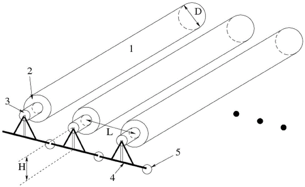
[0031] Such as figure 1 As shown, this embodiment relates to a high-speed surface drag reduction device, the drag reduction device is composed of several drag reduction units 6, and each drag reduction unit 6 includes: a rotating body 1, a bearing 2, a wheel shaft 3, and a fixed bracket 4 And the flexible connection device 5, the rotating body 1 in this embodiment is a cylindrical drum, the rotating body 1 is connected with the wheel shaft 3 through the bearing 2, the wheel shaft 3 is installed on the surface of the object through the fixed bracket 4, and the fixed bracket between the connected drag reducing units 4 are connected by a flexible connecting device 5.
[0032] In the specific implementation of the present invention, the ideal drag reduction effect depends on the setting of operating parameters, which include: the size of the wheel axle, the distance between the wheel axles, and how to arrange the space position of the wheel axles. These core parameters depend on ...
Embodiment 2
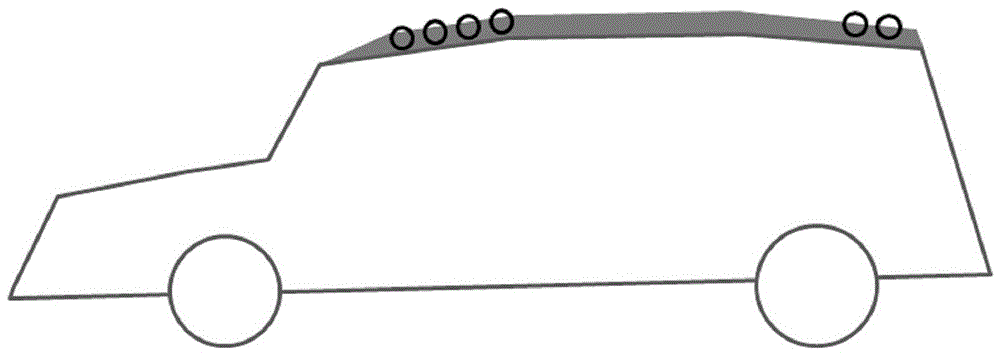
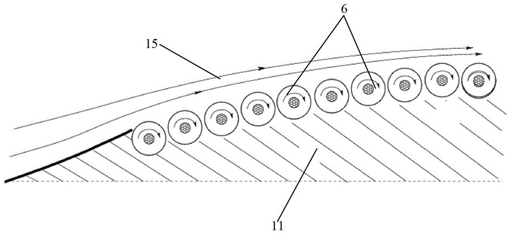
[0037] Such as image 3 , Figure 4 As shown, this embodiment relates to a high-speed surface drag reduction device, and the drag reduction device is composed of several drag reduction units 6, and each drag reduction unit 6 includes: a rotating body 1, a wheel shaft 3, and a bearing 2. In this embodiment, The rotating body 1 is a roller or a ball, and the rotating body 1 is connected with the wheel shaft 3 through a bearing, and the wheel shaft 3 is arranged on the surface 11 of the object.
[0038] When the object moves at a high speed, the surrounding fluid 15 will generate a large shear force on the surface 11 of the object due to its viscosity, thereby driving the rotating body 1 to rotate. It can be seen from the force analysis that the rotation of the rotating body 1 reduces the relative velocity between the moving body and the surrounding fluid 15, thereby reducing flow resistance and reducing energy consumption.
[0039] Such as image 3 , Figure 4 As shown, it i...
Embodiment 3
[0041] In this embodiment, the device with the same structure as that of Embodiment 1 or Embodiment 2 above is used on the surface of the ship immersed in the water body.
[0042] Usually, the speed of the ship is not very high, but because the dynamic viscosity coefficient of water is much larger than that of air, the drag reducing effect of the drag reducing structure of the present invention is very obvious. In this embodiment, the rotating body may adopt a roller structure on a relatively smooth surface, and may adopt a roller structure on a part of the relatively curved water-immersed surface.
PUM
 Abstract
Description
Claims
Application Information
 - R&D
- Intellectual Property
- Life Sciences
- Materials
- Tech Scout
- Unparalleled Data Quality
- Higher Quality Content
- 60% Fewer Hallucinations
Browse by: Latest US Patents, China's latest patents, Technical Efficacy Thesaurus, Application Domain, Technology Topic, Popular Technical Reports.
© 2025 PatSnap. All rights reserved.Legal|Privacy policy|Modern Slavery Act Transparency Statement|Sitemap|About US| Contact US: help@patsnap.com


