Novel high-speed surface resistance reduction device

A drag reduction device, high-speed technology, applied in the direction of mechanical equipment, fluid flow, etc., can solve the problems of large flow resistance and high energy consumption, and achieve the effect of reducing flow resistance, reducing energy consumption, and strong practicability

Active Publication Date: 2014-01-22
SHANGHAI JIAOTONG UNIV
View PDF5 Cites 7 Cited by
  • Summary
  • Abstract
  • Description
  • Claims
  • Application Information

AI Technical Summary

Problems solved by technology

[0010] Aiming at the deficiencies of the above-mentioned prior art, the present invention provides a new type of high-speed surface drag reduction device to solve the large flow resistance and high energy consumption caused by the large speed difference between the moving object and the surrounding fluid in the existing application The problem is to realize the important requirement of drag reduction through a simple and easy-to-operate device, with a wide range of applications, a simple and easy-to-operate structure, and at the same time based on sufficient theoretical research and good control of operating parameters, this technology has a good practical prospect

Method used


Image

  • Novel high-speed surface resistance reduction device
  • Novel high-speed surface resistance reduction device
  • Novel high-speed surface resistance reduction device

Examples


Embodiment 1

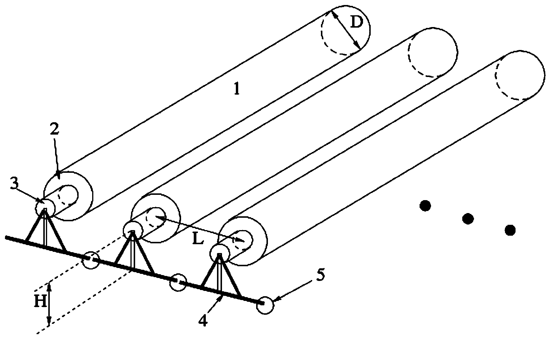
[0032] Such as figure 1 As shown, this embodiment relates to a new type of high-speed surface drag reduction device. The drag reduction device is composed of several drag reduction units 6, and each drag reduction unit 6 includes: a rotating body 1, a bearing 2, a wheel shaft 3, a fixed bracket 4 and the flexible connection device 5, the rotating body 1 in this embodiment is a cylindrical drum, the rotating body 1 is connected with the wheel shaft 3 through the bearing 2, the wheel shaft 3 is installed on the surface of the object through the fixed bracket 4, and the fixing between the connected drag reducing units The brackets 4 are connected by flexible connecting means 5 .

[0033] In the specific implementation of the present invention, the ideal drag reduction effect depends on the setting of operating parameters, which include: the size of the wheel axle, the distance between the wheel axles, and how to arrange the space position of the wheel axles. These core parameter...

Embodiment 2

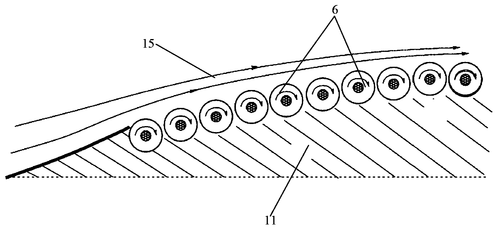
[0038] Such as image 3 , Figure 4 As shown, this embodiment relates to a new type of high-speed surface drag reduction device. The drag reduction device is composed of several drag reduction units 6, and each drag reduction unit 6 includes: a rotating body 1, a wheel shaft 3, and a bearing 2. In this implementation The rotating body 1 in the example is a roller or a ball, and the rotating body 1 is connected with the wheel shaft 3 through a bearing, and the wheel shaft 3 is arranged on the surface 11 of the object.

[0039] When the object moves at a high speed, the surrounding fluid 15 will generate a large shear force on the surface 11 of the object due to its viscosity, thereby driving the rotating body 1 to rotate. It can be seen from the force analysis that the rotation of the rotating body 1 reduces the relative velocity between the moving body and the surrounding fluid 15, thereby reducing flow resistance and reducing energy consumption.

[0040] Such as image 3 ,...

Embodiment 3

[0042] In this embodiment, the device with the same structure as that of Embodiment 1 or Embodiment 2 above is used on the surface of the ship immersed in the water body.

[0043] Usually, the speed of the ship is not very high, but because the dynamic viscosity coefficient of water is much larger than that of air, the drag reducing effect of the drag reducing structure of the present invention is very obvious. In this embodiment, the rotating body can adopt a roller structure on a relatively smooth surface, and a roller structure on a partially curved water-immersed surface.


PUM


Abstract

The invention relates to a novel resistance-reducing structure of a high-speed surface. The novel resistance-reducing structure is arranged on the surface of an object so as to reduce motion resistant of the object and comprises a wheel shaft and a rotating body, the wheel shaft is arranged on the surface of the object and connected with the surface of the object, and the rotating body is in sleeved connection with the wheel shaft. The novel resistance-reducing structure of the high-speed surface reduces relative motion speed difference between the moving object and surrounding fluid and has the advantages of reducing flow resistance of the moving object and energy consumption and being wide in applied range.

Description

technical field [0001] The invention relates to the field of fluid dynamics, in particular to a novel high-speed surface drag reducing device. Background technique [0002] In fluids, such as air or water, affected by the viscosity of the fluid, there is a large speed difference between the surface of a flying or moving object and the surrounding fluid. This relative motion will cause the fluid on the surface of the object to form a large velocity gradient, resulting in high flow friction resistance and great energy dissipation. For example, the kinetic energy loss of a missile flying in the atmosphere due to the aerodynamics will cause huge friction on the surface of the aircraft, resulting in severe ablation at high temperature. Therefore, it is very meaningful to reduce the relative velocity difference between the moving object and the surrounding fluid, reduce the surface velocity gradient, and solve the problems of large flow resistance and high energy consumption caus...

Claims


Application Information

Patent Timeline
Patent Type & Authority Applications(China)
IPC IPC(8): F15D1/00
Inventor 王利坡张强
Owner SHANGHAI JIAOTONG UNIV
Why Eureka
Try Eureka