Novel resistance-reducing structure of high-speed surface

A high-speed, new technology, applied in the direction of mechanical equipment, fluid flow, etc., can solve the problems of large flow resistance and high energy consumption, and achieve the effects of reducing flow resistance, wide application range, and reducing relative motion speed difference

Inactive Publication Date: 2012-11-14
SHANGHAI JIAO TONG UNIV
View PDF4 Cites 6 Cited by
  • Summary
  • Abstract
  • Description
  • Claims
  • Application Information

AI Technical Summary

Problems solved by technology

[0003] The purpose of the present invention is to provide a new high-speed surface drag reduction structure to solve the technical problems of large flow resistance and high energy consumption caused by the large speed difference between the moving object and the surrounding fluid in the existing application

Method used


Image

  • Novel resistance-reducing structure of high-speed surface
  • Novel resistance-reducing structure of high-speed surface
  • Novel resistance-reducing structure of high-speed surface

Examples


Embodiment 1

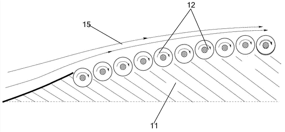
[0021] The novel surface drag-reducing structure of the present invention can be arranged on the surface of the ship immersed in the water body.

[0022] Usually, the speed of the ship is not very high, but because the dynamic viscosity coefficient of water is much larger than that of air, the drag reducing effect of the drag reducing structure of the present invention is very obvious. In this embodiment, the rotating body 14 may adopt a roller structure on a relatively smooth surface, and may adopt a roller structure on a part of a relatively curved water-immersed surface.

Embodiment 2

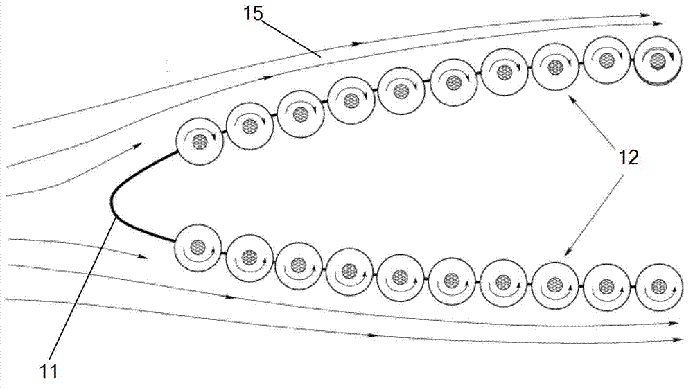
[0024] The novel surface drag-reducing structure of the present invention can be provided on a part of the surface of a high-speed moving object, such as a high-speed rail, an automobile, and the like.

[0025] The application environment of this embodiment is an ideal application environment for implementing the drag reducing structure of the present invention. Since most surfaces of the moving object are smooth and the movement is stable most of the time (without frequent stops and starts), the rotating body 14 can adopt a drum structure.


PUM


Abstract

The invention relates to a novel resistance-reducing structure of a high-speed surface. The novel resistance-reducing structure is arranged on the surface of an object so as to reduce motion resistant of the object and comprises a wheel shaft and a rotating body, the wheel shaft is arranged on the surface of the object and connected with the surface of the object, and the rotating body is in sleeved connection with the wheel shaft. The novel resistance-reducing structure of the high-speed surface reduces relative motion speed difference between the moving object and surrounding fluid and has the advantages of reducing flow resistance of the moving object and energy consumption and being wide in applied range.

Description

technical field [0001] The invention relates to the field of fluid dynamics, in particular to a novel high-speed surface drag-reducing structure. Background technique [0002] In fluids, such as air or water, affected by the viscosity of the fluid, there is a large speed difference between the surface of a flying or moving object and the surrounding fluid. This relative motion will cause the fluid on the surface of the object to form a large velocity gradient, resulting in high flow friction resistance and great energy dissipation. For example, the kinetic energy loss of a missile flying in the atmosphere due to the aerodynamics will cause huge friction on the surface of the aircraft, resulting in severe ablation at high temperature. Therefore, it is very meaningful to reduce the relative velocity difference between the moving object and the surrounding fluid, reduce the surface velocity gradient, and solve the problems of large flow resistance and high energy consumption c...

Claims


Application Information

Patent Timeline
Patent Type & Authority Applications(China)
IPC IPC(8): F15D1/00
Inventor 王利坡张强
Owner SHANGHAI JIAO TONG UNIV
Why Eureka
Try Eureka