

Air conditioner and its control method
An air conditioner, cooling and heating technology, applied in heating and ventilation control systems, refrigerators, heating methods, etc., can solve the neglect of rapid cooling and heating comfort requirements, system throttling components can not meet APF, energy efficiency ratio decline, etc. problems, to improve the heat pump energy efficiency ratio and system economic performance, solve the problem of throttling component system matching, and overcome the effect of slow cooling
- Summary
- Abstract
- Description
- Claims
- Application Information
AI Technical Summary
Problems solved by technology
Method used
Image

Examples
Embodiment 1
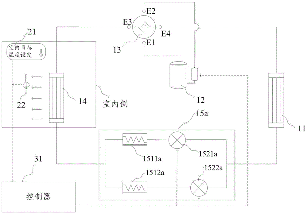
[0065] like figure 1 As shown, a first embodiment of an air conditioner of the present invention is proposed. The air conditioner of this embodiment includes an outdoor heat exchanger 11, a compressor 12, a four-way valve 13, an indoor heat exchanger 14, and a throttling device 15a; the outdoor heat exchanger 11, the compressor 12, the four-way valve 13, The indoor heat exchanger 14 and the throttling device 15a are connected by pipelines to form a closed air-conditioning circulation system. Wherein, the throttling device 15a further includes a first capillary 1511a, a second capillary 1512a, a first electromagnetic valve 1521a, and a second electromagnetic valve 1522a. The first capillary 1511a and the first electromagnetic valve 1521a are connected in series through a pipeline to form a first throttling branch, the second capillary 1512a and the second electromagnetic valve 1522a are connected in series to form a second throttling branch, and the first throttling branch Ro...
Embodiment 2
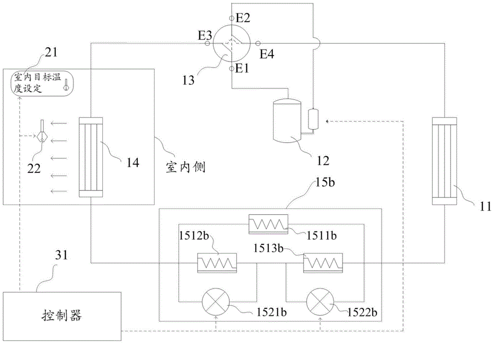
[0068] like figure 2 As shown, a second embodiment of the air conditioner of the present invention is proposed. In this embodiment, the same parts as those in the first embodiment will not be described here. The difference from the first embodiment is that the throttling device 15b in the second embodiment includes a first capillary 1511b, a second capillary 1512b, a third capillary 1513b, a first solenoid valve 1521b, and a second solenoid valve 1522b; The capillary 1511b alone forms the first throttling branch, the second capillary 1512b and the third capillary 1513b are connected in series to form the second throttling branch, and the first throttling branch and the second throttling branch are connected in parallel. At the same time, one end of the second capillary 1512b is connected to the indoor heat exchanger 14 through a pipe, and the first solenoid valve 1521b bypasses the second capillary 1512b. One end of the third capillary 1513b is connected to the outdoor heat...
Embodiment 3
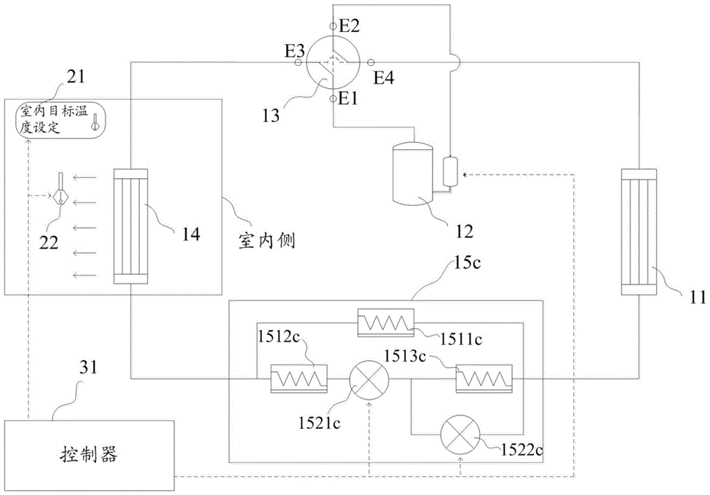
[0071] like image 3 As shown, a second embodiment of the air conditioner of the present invention is proposed. In this embodiment, the same parts as those in Embodiment 1 and Embodiment 2 will not be described here. The difference in this embodiment is that the throttling device 15c includes a first capillary 1511c, a second capillary 1512c, a third capillary 1513c, a first solenoid valve 1521c, and a second solenoid valve 1522c; the first capillary 1511c alone constitutes the first joint In the flow branch, the second capillary 1512c, the first electromagnetic valve 1521c and the second capillary 1512c are sequentially connected in series through pipelines to form a second throttling branch, and the first throttling branch and the second throttling branch are connected in parallel. One end of the second capillary 1512c is connected to the indoor heat exchanger 14 through a pipeline, and one end of the third capillary 1513c is connected to the outdoor heat exchanger 11 throu...
PUM
 Abstract
Description
Claims
Application Information