Remote control circuit detection circuit for negative control terminal

A detection circuit and remote control circuit technology, which is applied in the direction of measuring electricity, measuring electrical variables, measuring devices, etc., can solve the problems of not being able to know the status of the remote control circuit in advance, and cannot judge whether the circuit is correct or not in advance, so as to achieve simple and reliable implementation. The effect of small space and low cost

Active Publication Date: 2016-09-07
WILLFAR INFORMATION TECH CO LTD
View PDF8 Cites 0 Cited by
  • Summary
  • Abstract
  • Description
  • Claims
  • Application Information

AI Technical Summary

Problems solved by technology

The disadvantage of this method is that the status of the remote control loop cannot be known in advance, and the correctness of the loop cannot be judged in advance. The specific situation can only be known after the remote control is executed.

Method used


Image

  • Remote control circuit detection circuit for negative control terminal
  • Remote control circuit detection circuit for negative control terminal
  • Remote control circuit detection circuit for negative control terminal

Examples


Embodiment Construction

[0010] One end of the invention is connected with the normally open contact end of the remote control output relay, and the other end is connected with the common contact end of the relay.

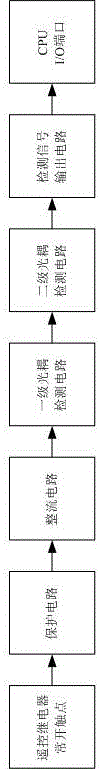
[0011] The invention includes a remote control output relay, a CPU, a protection circuit, a rectification circuit, an optocoupler detection circuit and a detection signal output circuit.

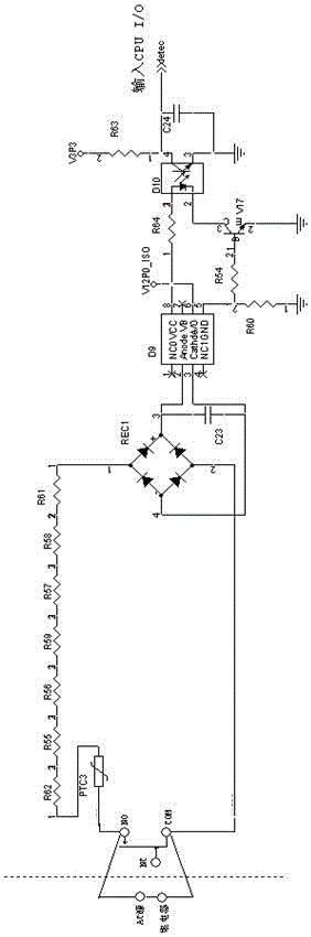
[0012] The existing equipment is connected to the normally open contact of the remote control output relay: the normally open contact end of the remote control output relay is connected to one input end of the rectification circuit through the protection circuit, and the common contact end of the relay is connected to the other input end of the rectification circuit Connection; the output end of the rectification circuit is connected with the input end of the optocoupler detection circuit, the output end of the optocoupler detection circuit is connected with the input end of the detection signal output ci...


PUM


Abstract

The invention discloses a remote control loop detection circuit for a negative control terminal, comprising a remote control output relay, a CPU, a protection circuit, a rectifier circuit, a primary optocoupler detection circuit, a detection signal output circuit, and a normally open contact of the remote control output relay The terminal is connected to the protection circuit, the protection circuit is connected to the rectification circuit, the rectification circuit is connected to the first-level optocoupler detection circuit, the first-level optocoupler detection circuit is connected to the detection signal output circuit, and the detection signal output circuit is connected to the I / O port of the CPU. The invention is connected between the normally open contact end and the common contact end of the remote control output relay. The present invention does not require feedback signals from external equipment, and can know in advance whether the state of the loop is normal or not before remote control execution, and ensures that the tripping action of the terminal can be executed normally. The invention has simple circuit, small occupied space, simple and reliable realization, and low cost.

Description

technical field [0001] The invention relates to a remote control loop detection circuit, in particular to a remote control loop detection circuit for a negative control terminal. Background technique [0002] At present, the terminal knows the execution state of the remote control output through the remote signaling signal fed back by the external execution device. The disadvantage of this method is that the status of the remote control loop cannot be known in advance, and the correctness of the loop cannot be judged in advance. The specific situation can only be known after the remote control is executed. Contents of the invention [0003] The object of the present invention is to provide a remote control loop detection circuit for a negative control terminal which provides a remote control loop state for the terminal and does not require external equipment to provide feedback signals. [0004] The remote control loop detection circuit for negative control terminals prov...

Claims


Application Information

Patent Timeline
Patent Type & Authority Patents(China)
IPC IPC(8): G01R31/00
Inventor 刘志勇汤可李航
Owner WILLFAR INFORMATION TECH CO LTD
Why Eureka
Try Eureka