Method and device for measuring difference modulation rate of power generation set

A technology of generator set and differential rate, which is applied in the field of electric power, can solve problems such as difficult implementation and inaccurate results, and achieve the effect of improving stability, improving test efficiency and accuracy

Active Publication Date: 2014-01-22
STATE GRID CORP OF CHINA +1
View PDF4 Cites 11 Cited by
  • Summary
  • Abstract
  • Description
  • Claims
  • Application Information

AI Technical Summary

Problems solved by technology
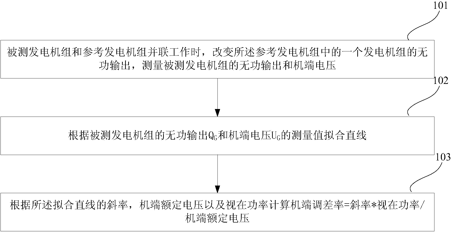
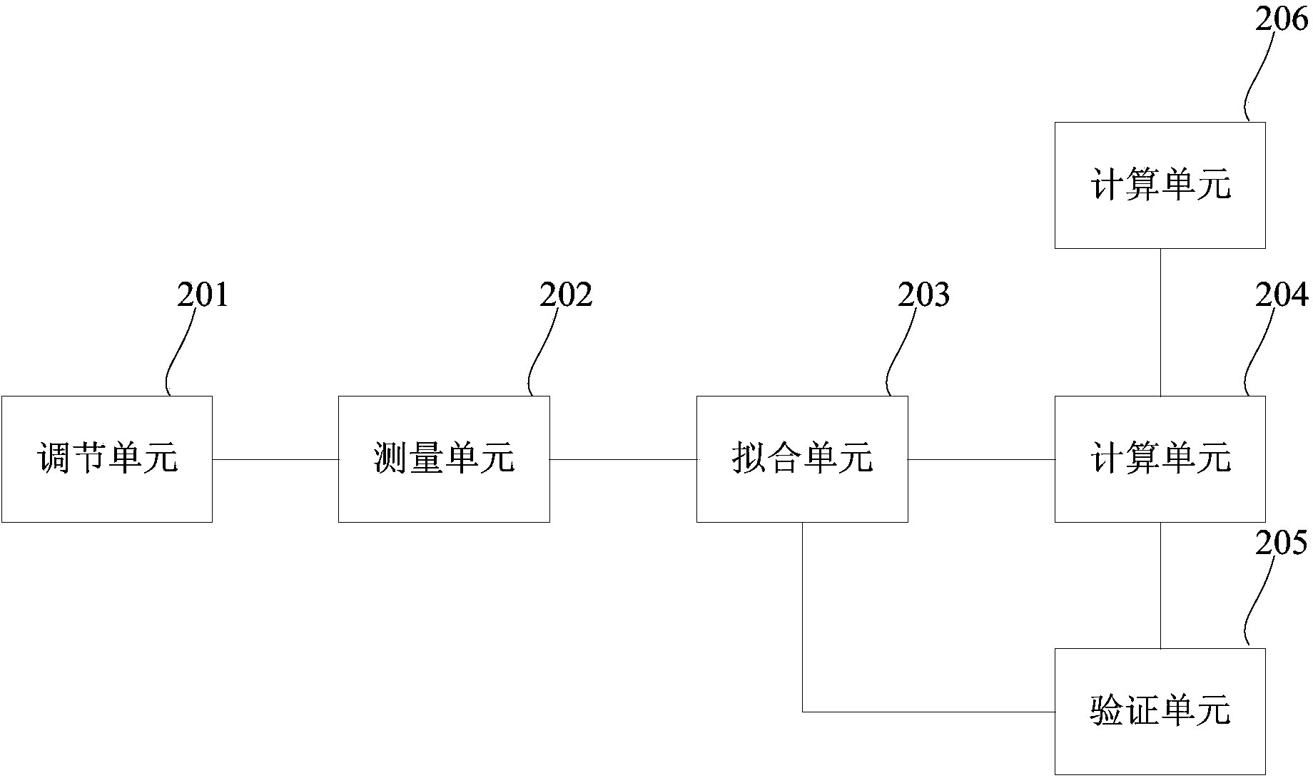
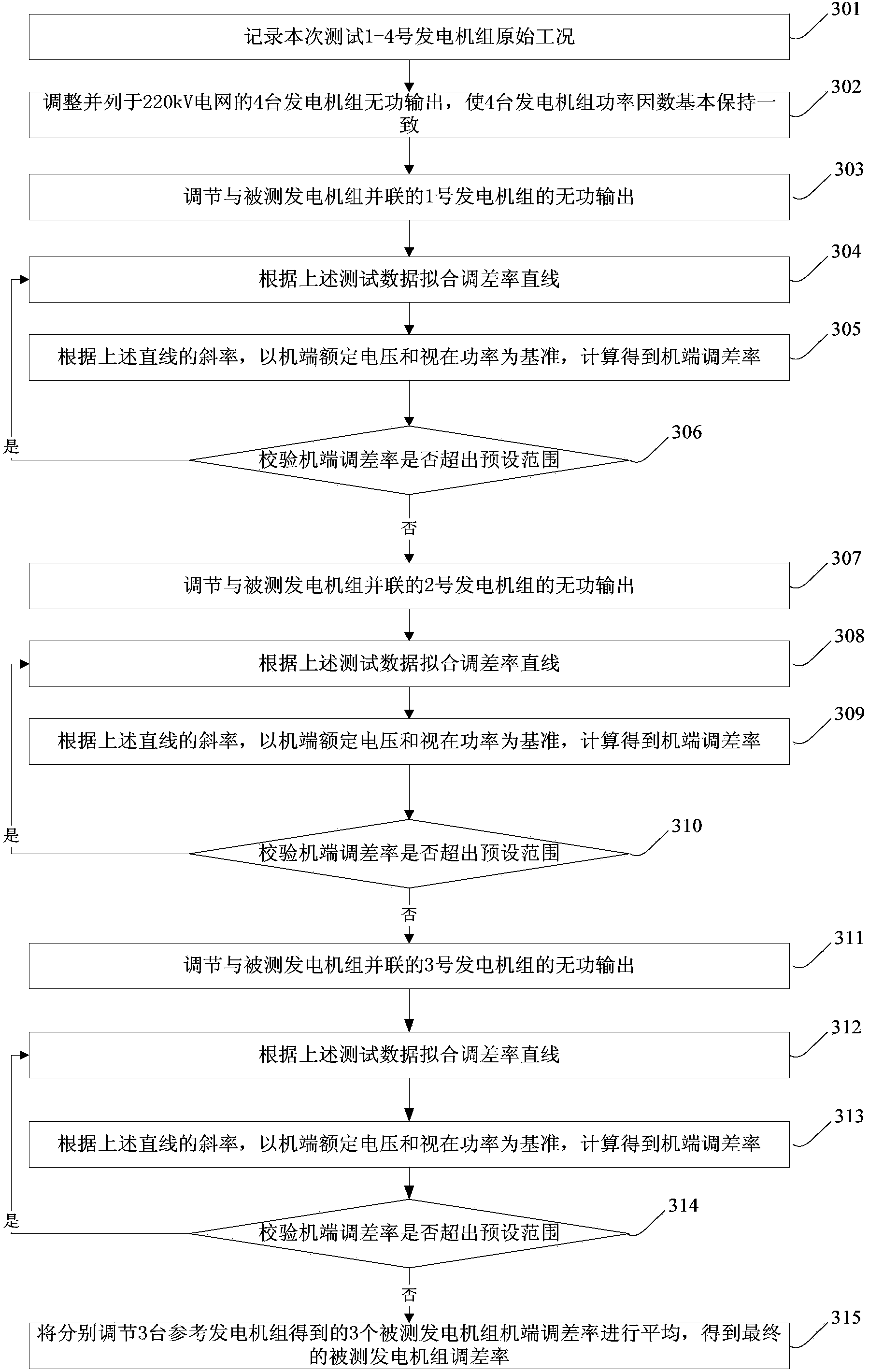
[0019] In order to solve the problem of inaccurate results of the calculation method of the differential rate of the generator in the prior art, and the existing actual measurement method has many limitations and is difficult to implement, the embodiment of the present i

Method used


Image

  • Method and device for measuring difference modulation rate of power generation set
  • Method and device for measuring difference modulation rate of power generation set
  • Method and device for measuring difference modulation rate of power generation set

Examples


Embodiment Construction

[0048] The following description will enable any person skilled in the art to utilize the present invention. The descriptions provided in the specific embodiments and applications are examples only. Various extensions and combinations of the embodiments described herein will be apparent to those skilled in the art, and the general principles defined herein may be applied to other embodiments and applications without departing from the spirit and scope of the invention . Thus, the present invention is not limited to the embodiments shown, but the present invention covers the widest scope consistent with the principles and features shown herein.

[0049] The detailed description below is presented in the form of flow diagrams, logical modules and other symbolic manipulation representations that can be executed on a computer system. A program, computer-implemented step, logic block, procedure, etc., is conceived herein to be a self-consistent sequence of one or more steps or in...


PUM


Abstract

The invention relates to the technical field of electric power, in particular to a method and a device for measuring a difference modulation rate of a power generation set. The method comprises the steps of changing reactive output of a power generation set in reference power generation sets when a power generation set to be measured and the reference power generation sets operate in parallel, measuring reactive output and generator terminal voltage of the power generation set to be measured, fitting a straight line according to measured values of the reactive output and the generator terminal voltage of the power generation set to be measured, and calculating the generator terminal difference modulation rate of the power generation set to be measured according to a slope of the fitting straight line, generator terminal rated voltage and apparent power by adopting a formula that the generator terminal difference modulation rate is equal to slope * apparent power/generator terminal rated voltage. With the adoption of the method and the device, the difference modulation rate of the power generation set is measured accurately when the power generation set is in a normal on-load working condition; the test efficiency and accuracy are greatly improved; the stable and reasonable reactive power distribution of the power generation sets in parallel operation is facilitated; and the stability of an electric system is improved.

Description

technical field [0001] The invention relates to the field of electric power technology, in particular to a method and device for measuring the difference rate of a generating set. Background technique [0002] When the external load disturbance of the generator disappears, and after a long enough time, after the excitation system stabilizes, the generator terminal voltage U G and stator reactive current I Q The relationship between them is usually called the generator voltage regulation characteristics, or the external characteristics of the generator. Such as Figure 5 Shown is a schematic diagram of generator voltage regulation characteristics in the prior art, with the reactive current I Q The increase of the machine terminal voltage U G Decline, the extent of its decline is described by the voltage difference rate D. "DL / T843-2010 Large Turbine Generator Excitation System Technical Conditions" defines the voltage difference rate as the generator. When the power facto...

Claims


Application Information

Patent Timeline
IPC IPC(8): G01R31/34
Inventor 史扬苏为民付宏伟赵焱徐正龙
Owner STATE GRID CORP OF CHINA
Why Eureka
Try Eureka