Pulse compression method for field of linear frequency modulation signals

A chirp signal, pulse compression technology, applied in radio wave measurement systems, instruments, etc., can solve the problems of signal-to-noise ratio loss, poor distance resolution, poor image quality, etc.

Active Publication Date: 2014-01-22
BEIJING INST OF RADIO METROLOGY & MEASUREMENT
View PDF1 Cites 6 Cited by
  • Summary
  • Abstract
  • Description
  • Claims
  • Application Information

AI Technical Summary

Problems solved by technology

[0006] In the prior art, pulse compression methods for chirp signals have the following dis

Method used


Image

  • Pulse compression method for field of linear frequency modulation signals
  • Pulse compression method for field of linear frequency modulation signals
  • Pulse compression method for field of linear frequency modulation signals

Examples


Embodiment Construction

[0051] The content of the invention of the present invention will be further described below in conjunction with the accompanying drawings and embodiments.

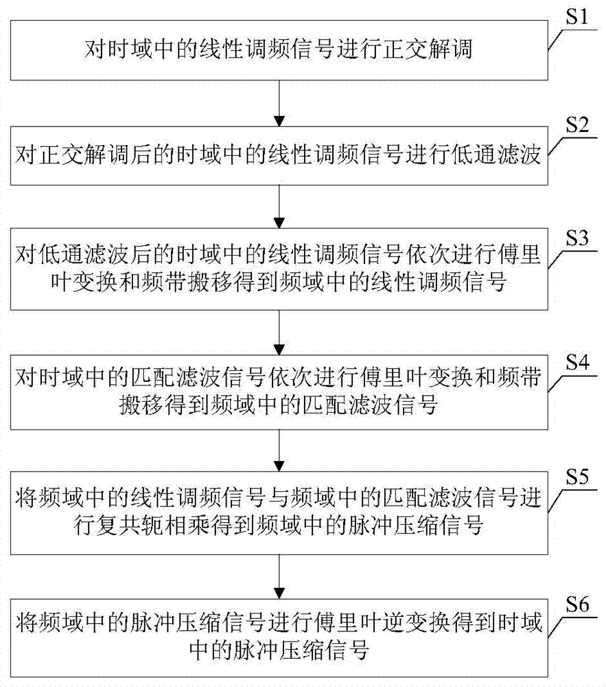
[0052] Such as figure 1 As shown, the pulse compression method used in the frequency domain of the chirp signal provided by this embodiment includes the following steps:

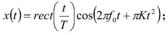
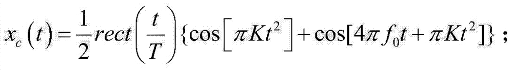
[0053] S1: Perform quadrature demodulation on the chirp signal in the time domain;

[0054] S2: performing low-pass filtering on the chirp signal in the time domain after quadrature demodulation;

[0055] S3: sequentially performing Fourier transform and frequency band shifting on the low-pass filtered chirp signal in the time domain to obtain the chirp signal in the frequency domain;

[0056] S4: sequentially perform Fourier transform and frequency band shift on the matched filter signal in the time domain to obtain the matched filter signal in the frequency domain;

[0057] S5: performing complex conjugate multiplication of the chirp signal in the ...


PUM


Abstract

The invention discloses a pulse compression method for the field of linear frequency modulation signals. The method comprises the following steps: the orthogonal demodulation is implemented for the linear frequency modulation signals in the time domain; the low-pass filtering is implemented for the orthogonally demodulated linear frequency modulation signals in the time domain; the Fourier transform and the frequency band transfer are sequentially implemented for the low-pass filtered linear frequency modulation signals in the time domain to obtain linear frequency modulation signals in the frequency domain; the Fourier transform and the frequency band transfer are sequentially implemented for matched filtering signals in the time domain to obtain matched filtering signals in the frequency domain; the matched filtering signals in the time domain are converted to the matched filtering signals in the frequency domain; the complex conjugate multiplication is implemented for the linear frequency modulation signals in the frequency domain and the matched filtering signals in the frequency domain to obtain pulse compression signals in the frequency domain; and the Fourier inversion is implemented for the pulse compression signals in the frequency domain to obtain pulse compression signals in the time domain. The pulse compression method of the invention can improve the range resolution, reduce the loss of signal-to-noise ratio, and modify the image quality.

Description

technical field [0001] The invention relates to the technical field of pulse compression, in particular to a pulse compression method used in the frequency domain of linear frequency modulation signals. Background technique [0002] With the development of remote sensing technology, the requirements for performance indicators such as radar or fuze range, resolution capability and measurement accuracy are getting higher and higher. If the resolution capability and measurement accuracy of the radar system are to be improved, the radar signal is required to have a large time-width-bandwidth product. However, due to the limitation of the peak power of the transmitting equipment and the feeding equipment of the radar system, the radar signal with higher energy can only be obtained by increasing the pulse width. However, the product of the instant width and the bandwidth of the pulse width of the single-carrier frequency pulse signal is close to 1, so a large pulse width and a la...

Claims


Application Information

Patent Timeline
IPC IPC(8): G01S7/28
CPCG01S7/285
Inventor 李秀华刘李娟张峰李宏宇高希权李闯
Owner BEIJING INST OF RADIO METROLOGY & MEASUREMENT
Why Eureka
Try Eureka