Full-aircraft beam frame type reduction stiffness combination modeling method

A modeling method and a full-machine technology, applied in special data processing applications, instruments, electrical digital data processing, etc., can solve problems such as difficult to accurately simulate the dynamic characteristics of complex structures, few degrees of freedom, huge units and degrees of freedom, etc. , to achieve the effect of convenient variable parameter analysis, convenient adjustment, and reduced calculation scale

Active Publication Date: 2014-01-22
XIAN AIRCRAFT DESIGN INST OF AVIATION IND OF CHINA
View PDF2 Cites 5 Cited by
  • Summary
  • Abstract
  • Description
  • Claims
  • Application Information

AI Technical Summary

Problems solved by technology

The beam frame model has a simple structure and few degrees of freedom. The disadvantage is that it is necessary to accurately calculate the section stiffness data through single closed chamber, multi-closed chamber or force deformation method, so it is difficult to accurately simulate the dynamic characteristics of some complex structures, and the modeling accuracy is relatively low. Low; the rod-plate model has a great advantage in modeling accuracy, but the u

Method used


Image

  • Full-aircraft beam frame type reduction stiffness combination modeling method
  • Full-aircraft beam frame type reduction stiffness combination modeling method
  • Full-aircraft beam frame type reduction stiffness combination modeling method

Examples


Embodiment

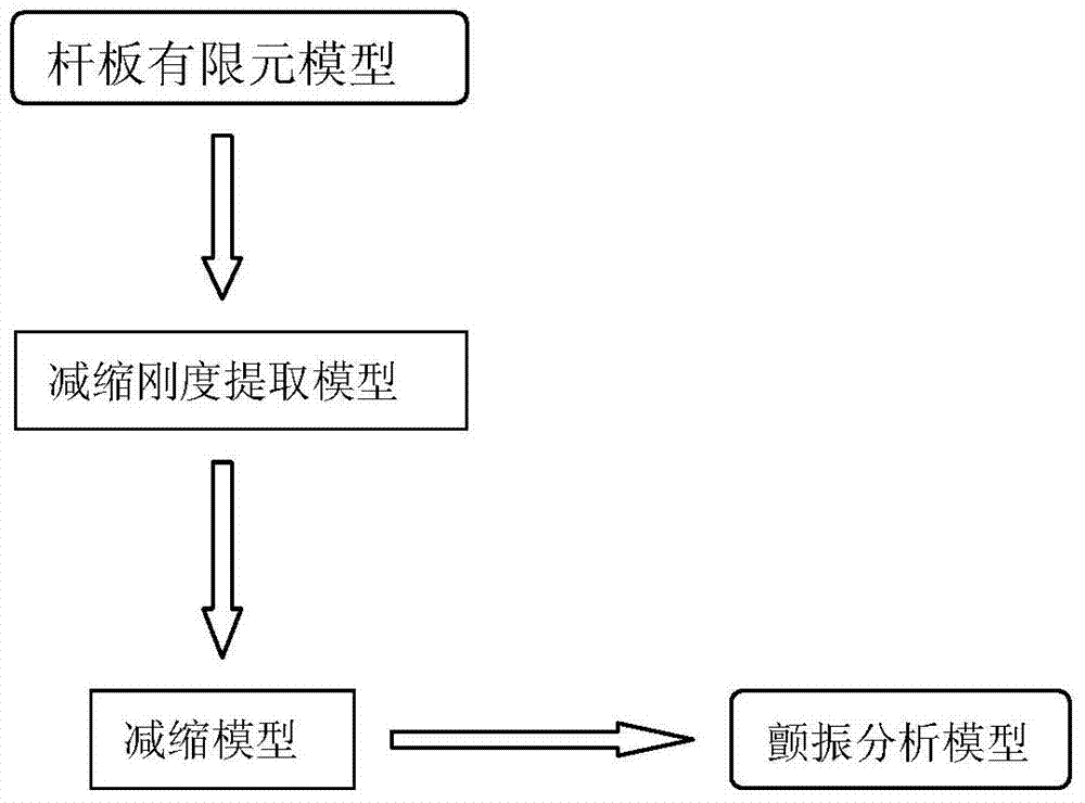
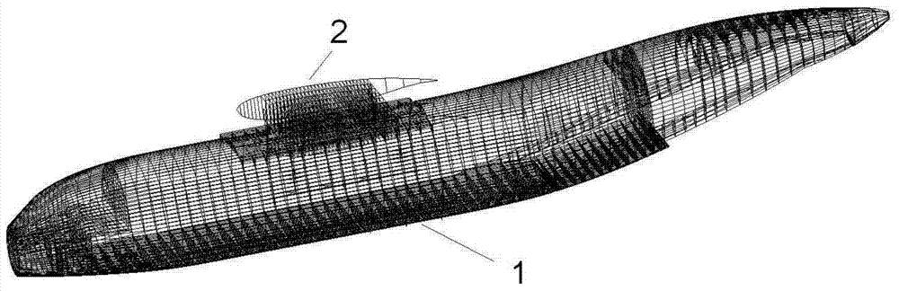
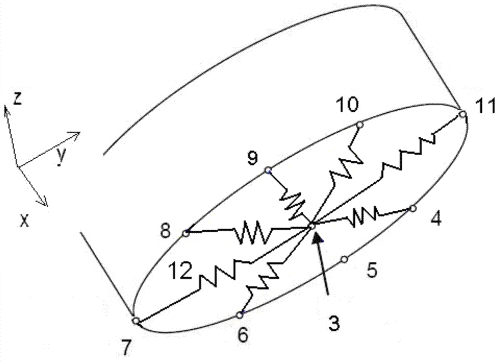
[0019] First, a reduced stiffness model is established. Select the finite element model of fuselage 1 and wing-body connection 2 as the research object, see figure 2 , set the reference point 3 at the centroid position of each frame section of the rod-plate finite element model, and use the RBE3 rigid body element 12 to reduce the corresponding section stiffness, the reduction form is as follows image 3 As shown, through the weighted average of nodes 4, 5, 6, 7, 8, 9, 10, and 11, the section stiffness is "condensed" to the reference point 3.

[0020] Secondly, output the stiffness matrix KAA corresponding to the reduced model through the DMAP statement. Since the stiffness matrix KAA does not contain reference point information, it is necessary to introduce the reference point information into the stiffness matrix KAA to generate the STIFF matrix.

[0021] Then, use the reference point, the STIFF matrix, and the quality characteristics corresponding to the rod-plate model t...


PUM


Abstract

The invention belongs to the technical field of aeroelasticity, and relates to a full-aircraft beam frame type reduction stiffness combination modeling method. A reduction method is used for obtaining a stiffness matrix of a connecting portion of a rear fuselage large opening and a wing body, and therefore the problem that accurate stiffness data of the complex structures are difficult to obtain through a previous computing method; moreover, a full-aircraft beam frame type reduction stiffness combination model is established in combination with a beam frame model for wings, a vertical tail, a horizontal tail and other components, as a result, accurate simulation of full-aircraft stiffness characteristics is realized, the computing scale is greatly reduced, computing efficiency is improved, model adjustment and parameter variation analysis after a full-aircraft ground resonance test are facilitated, the deficiency of the current modeling technology is remedied, and a novel path is opened up for aeroelastic simulation modeling.

Description

technical field [0001] The invention belongs to the technical field of aeroelasticity, and relates to a beam frame-reduced stiffness combined modeling method of the whole machine. Background technique [0002] At present, the commonly used finite element models in flutter analysis include beam-frame model and bar-plate model. The beam frame model has a simple structure and few degrees of freedom. The disadvantage is that it is necessary to accurately calculate the section stiffness data through single closed chamber, multi-closed chamber or force deformation method, so it is difficult to accurately simulate the dynamic characteristics of some complex structures, and the modeling accuracy is relatively low. Low; the rod-plate model has great advantages in modeling accuracy, but the units and degrees of freedom involved are extremely large, and the amount of calculation is too large, which is not convenient for variable parameter analysis and model correction. In the whole ma...

Claims


Application Information

Patent Timeline
IPC IPC(8): G06F17/50
Inventor 赵冬强洪兆贵
Owner XIAN AIRCRAFT DESIGN INST OF AVIATION IND OF CHINA
Why Eureka
Try Eureka