Emergency protection circuit with indicator light

An emergency protection and indicator light technology, applied in emergency protection circuit devices, automatic disconnection emergency protection devices, circuit devices, etc., can solve the problem of damage to the protection switch, poor safety and reliability, and failure of the protection switch lock to protect function and other problems, to achieve the effect of reliable cutting

Active Publication Date: 2016-04-27
ANHUI YINGTE ELECTRONICS
View PDF3 Cites 0 Cited by
  • Summary
  • Abstract
  • Description
  • Claims
  • Application Information

AI Technical Summary

Problems solved by technology

[0002] At present, most of the existing emergency protection circuits use protection switches. The protection switch is only a mechanical self-locking switch. In the case of high frequency of use, it is easy to cause damage to the protection switch itself, so that the lock of the protection switch cannot play a protective role. ; At the same time, the protection switch has a simple structure and cannot realize electronic self-locking. After protection, the protection switch itself can restore power supply, and the safety and reliability of protection are poor.
In addition, the current protection switch uses a mechanical stroke to turn on and off. Due to the short action stroke, it is difficult for people to find out what state the protection switch is in.

Method used


Image

  • Emergency protection circuit with indicator light
  • Emergency protection circuit with indicator light
  • Emergency protection circuit with indicator light

Examples


Embodiment Construction

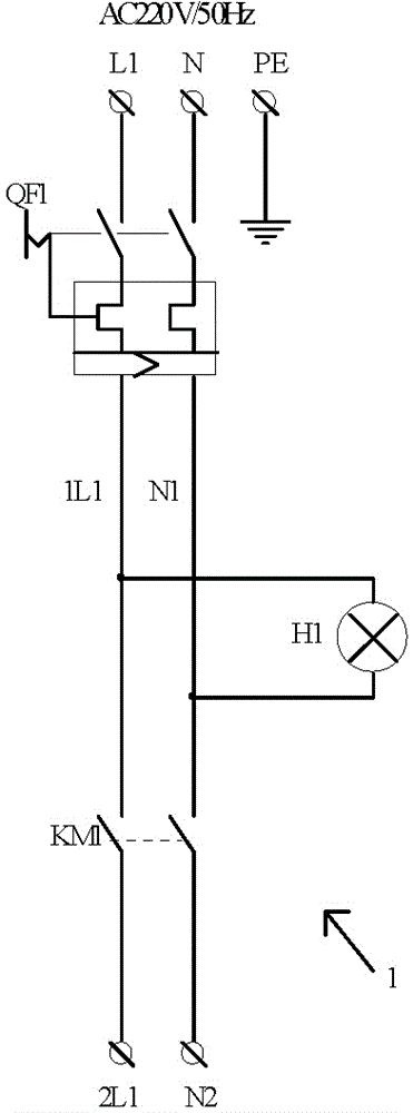
[0013] An emergency protection circuit with an indicator light, including a main circuit 1, the main circuit 1 adopts an air switch QF1, one end of which is connected to the grid power supply 220V AC, and the other end is connected to the input end of the AC contactor KM1, and the AC contactor KM1 The output terminal outputs 220V AC power to the electrical equipment; the indication circuit 2, the operation control circuit 3, and the emergency control circuit 4 are all connected between the air switch QF1 and the AC contactor KM1. It also includes the power indicator light H1, which is connected between the air switch QF1 and the AC contactor KM1, such as figure 1 As shown, when the air switch QF1 is closed, the power indicator H1 is on.

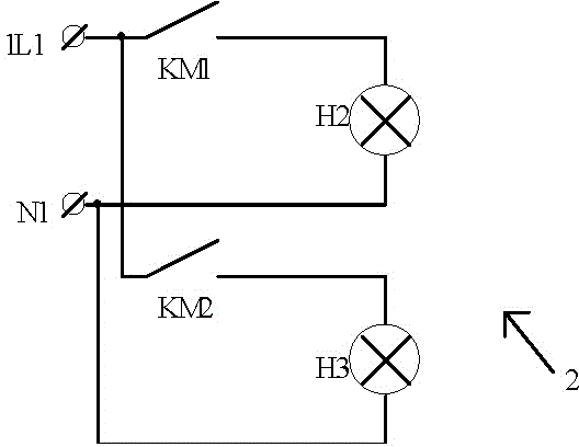
[0014] Such as figure 2 As shown, the indicator circuit 2 includes a running indicator light H2 and an emergency indicator light H3, and the running indicator light H2 is connected in series with the normally open contact of the AC contacto...


PUM


Abstract

The invention relates to an emergency protection circuit provided with an indicator light. The emergency protection circuit comprises a main loop, wherein the main loop adopts an air switch QF1, one end of the air switch is connected with 220V alternating current of a grid power supply, the other end of the air switch is connected with an input end of an alternating current contactor KM1, and an output end of the alternating current contactor KM1 outputs 220V alternating current to electric equipment; and an indication loop, an operation control loop and an emergency control loop are all connected between the air switch QF1 and the alternating current contactor KM1. When the electric equipment breaks down, a power supply can be rapidly, safely and reliably cut off; and when emergency circumstance happens, an emergency button is pressed down, the alternating current contactor KM1 loses power, input of a working power supply is cut off, and the emergency indicator light H3 is lightened simultaneously. After emergency, the emergency indicator light H3 is used for indication; the alternating current contactor KM1 with an arc extinguishing function is adopted; a self-locking stop switch is not adopted, but an emergency relay KM2 is adopted for self locking; and after emergency, the grid power supply can be started after the air switch is reset.

Description

technical field [0001] The invention relates to an emergency protection circuit, in particular to an emergency protection circuit with an indicator light. Background technique [0002] At present, most of the existing emergency protection circuits use protection switches. The protection switch is only a mechanical self-locking switch. In the case of high frequency of use, it is easy to cause damage to the protection switch itself, so that the lock of the protection switch cannot play a protective role. At the same time, the protection switch has a simple structure and cannot realize electronic self-locking. After protection, the protection switch itself can restore power supply, and the safety and reliability of protection are relatively poor. In addition, at present, the protection switch adopts a mechanical stroke to turn on and off. Due to the short action stroke, it is difficult for people to find out what state the protection switch is in. Contents of the invention ...

Claims


Application Information

Patent Timeline
Patent Type & Authority Patents(China)
IPC IPC(8): H02H3/04
Inventor 万波董建军赵立群陆松涛
Owner ANHUI YINGTE ELECTRONICS
Why Eureka
Try Eureka