Modular structure and module construction method

A construction method and structure technology, which is applied in nuclear engineering, industrial buildings, manufacturing reactors, etc., can solve the problems of inability to obtain precision, inability to hang component parts, etc., and achieve the effect of efficient coating

Inactive Publication Date: 2015-11-25
HITACHI LTD
View PDF11 Cites 0 Cited by
  • Summary
  • Abstract
  • Description
  • Claims
  • Application Information

AI Technical Summary

Problems solved by technology

However, the suspension mechanism cannot suspend components that overlap in the vertical direction, so there is a problem that the application is limited
In addition, when there are many overlapping components, there is a problem that the accuracy of alignment cannot be obtained.

Method used


Image

  • Modular structure and module construction method
  • Modular structure and module construction method
  • Modular structure and module construction method

Examples


Embodiment Construction

[0077] Hereinafter, the present invention will be described in detail using embodiments shown in the drawings. The components, types, combinations, shapes, and relative arrangements thereof described in this embodiment are merely illustrative examples unless they are definitive descriptions, and do not limit the scope of the present invention thereto.

[0078] Hereinafter, embodiments of the modular structure and the construction method of the present invention will be described in detail with reference to the drawings.

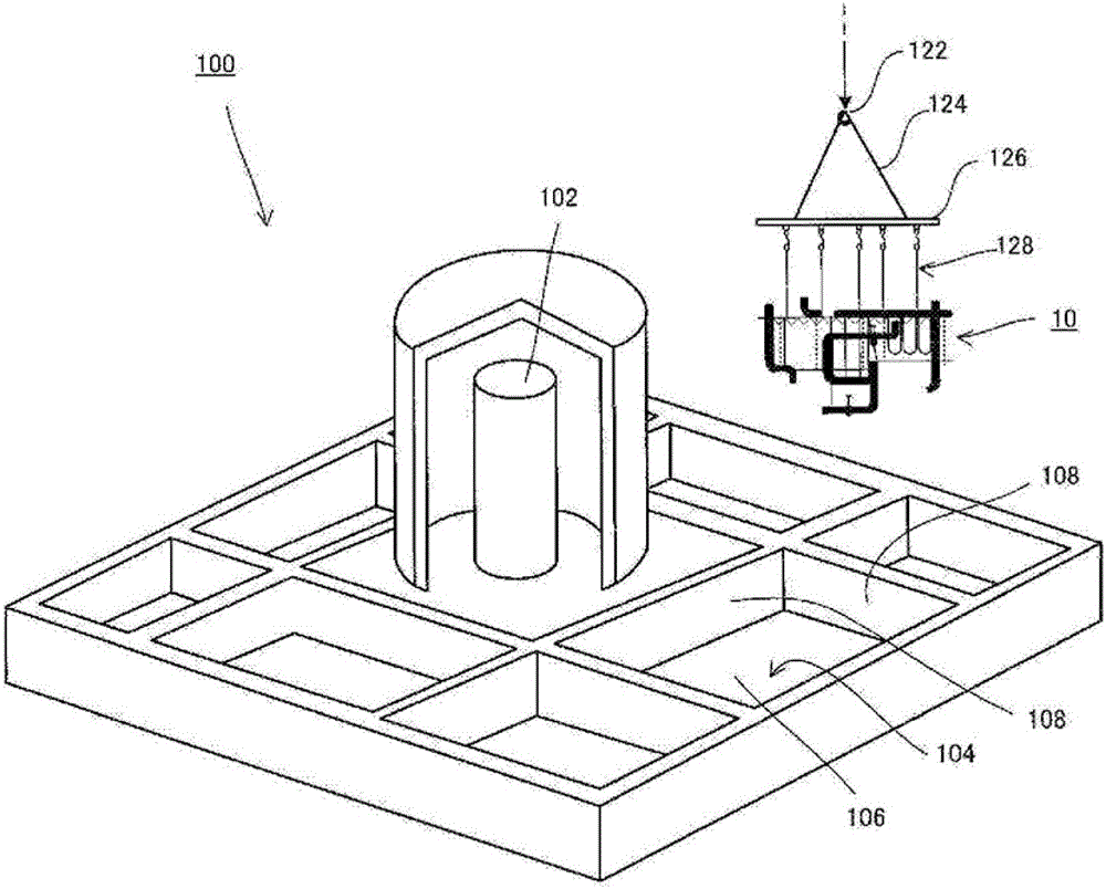
[0079] figure 1 It is an explanatory diagram of a nuclear power plant. figure 2 It is an explanatory drawing of the module structure which concerns on 1st Embodiment. Such as figure 1 As shown, the nuclear power plant 100 will be described below as an example of a factory to which the module structure of the present invention is imported. The nuclear power plant 100 is composed of a plurality of equipment equipment 110 except for the reactor pressure v...


PUM


Abstract

In order to provide a modular structure and a modular construction method capable of temporarily supporting an equipment component in a layout position of a compartment, suppressing interference with a floor surface to the minimum, and efficiently performing a work for the floor surface such as a painting, the modular structure includes: a wire rope (16) that is capable of hanging an equipment component (14) arranged in a compartment (104) of a plant and has a length adjusted depending on a layout arrangement position of the equipment component (14) in the compartment (104); and a beam (12) arranged in the compartment (104), the wire rope (16) being installed in the beam (12) to hang the equipment component (14), wherein the equipment component (14) can be temporarily supported in the arrangement position.

Description

technical field [0001] The present invention relates to a modular structure and a modular construction method using the same, and more particularly to a modular structure and a modular construction method suitable for plant construction such as nuclear power generation. Background technique [0002] Factories such as nuclear power plants are housed in buildings with a reinforced concrete structure, and the buildings are divided into multiple rooms according to the types of equipment and equipment. The construction method of the conventional factory as described above roughly includes: forming a plurality of stages in which the factory building is arbitrarily divided according to the installation of equipment and equipment; stage. [0003] Fig. 12, Fig. 13 and Fig. 14 show the explanatory diagrams of the construction stages of the factory in the prior art, Fig. 12-A is the sidewall pouring stage, Fig. 12-B is the stage of equipment and machine moving in, and Fig. 12-C is the...

Claims


Application Information

Patent Timeline
Patent Type & Authority Patents(China)
IPC IPC(8): E04H5/02G21C13/00
CPCE04H5/02G21C21/00G21D1/00Y02E30/00
Inventor 佐藤耕二江幡伸一牧田辰雄今冈静男吉崎正俊井出桥成年田村谦介
Owner HITACHI LTD
Why Eureka
Try Eureka