
Workpiece positioning component

A technology for positioning components and workpieces, which is applied in the direction of workpiece clamping devices and manufacturing tools, which can solve the problems of low precision and inaccurate movement of workpieces, and achieve the effect of improving machining accuracy and precise movement

Inactive Publication Date: 2014-01-29
SIP GOLDWAY TECH
View PDF4 Cites 2 Cited by
  • Summary
  • Abstract
  • Description
  • Claims
  • Application Information

AI Technical Summary

Problems solved by technology

[0002] When the existing positioning device is processing the workpiece, it often cannot move accurately. The precision of the workpiece processed in this way is not high, and it cannot meet people's requirements well.

Method used


Image

  • Workpiece positioning component
  • Workpiece positioning component

Examples


Embodiment Construction

[0017] The present invention will be described in detail below in conjunction with the implementations shown in the drawings, but it should be noted that these implementations are not limitations of the present invention, and those of ordinary skill in the art based on the functions, methods, or structural changes made by these implementations Equivalent transformations or substitutions all fall within the protection scope of the present invention.

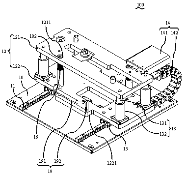
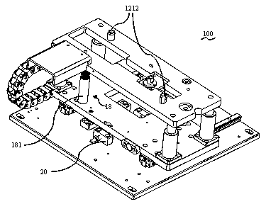
[0018] Such as figure 1 , figure 2 as shown, figure 1 It is a three-dimensional schematic diagram of the workpiece positioning member 100 in this embodiment, figure 2 for figure 1 The three-dimensional schematic diagram of another angle of the workpiece positioning member 100 is shown, which includes: a base plate 10 supporting other components thereon. Two sliding rails 11 arranged in parallel are arranged on the base plate 10 , and the cross section of the sliding rails 11 is an "I" shape.

[0019] The workpiece positioni...


PUM


Abstract

The invention provides a workpiece positioning component which comprises a substrate, a sliding rail, bearing plates and a power system. The sliding rail is arranged on the substrate, the bearing plates comprise the upper bearing plate and the lower bearing plate, the bottom of the lower bearing plate is provided with a groove channel matched with the sliding rail, and the lower bearing plate is connected with the upper bearing plate through a plurality of connecting rods; the power system comprises an air cylinder arranged on the upper bearing plate and a transmission belt, and the power system drives the bearing plates to move along the sliding rail. The workpiece positioning component is accurate in movement, and the machining accuracy of a workpiece is improved.

Description

technical field [0001] The invention relates to a positioning device, in particular to a workpiece positioning device. Background technique [0002] When the existing positioning device is processing the workpiece, it often cannot accurately move the position, and the precision of the workpiece processed in this way is not high, and cannot well meet people's requirements. Contents of the invention [0003] The object of the present invention is to provide a workpiece positioning member. [0004] In order to achieve the purpose of the above invention, a workpiece positioning member of the present invention, the workpiece positioning member includes: a base plate; a slide rail, which is located on the base plate; a pressure bearing plate, which includes an upper pressure bearing plate and a lower pressure bearing plate, The bottom of the lower pressure bearing plate is provided with a groove matching the slide rail, and the lower pressure bearing plate is connected with the...

Claims


Application Information

Patent Timeline
Patent Type & Authority Applications(China)
IPC IPC(8): B25B11/00
CPCB25B11/00
Inventor 李佳
Owner SIP GOLDWAY TECH
Features
  • Generate Ideas
  • Intellectual Property
  • Life Sciences
  • Materials
  • Tech Scout
  • Unparalleled Data Quality
  • Higher Quality Content
  • 60% Fewer Hallucinations
Learn More