
Forming mold for precast beam plate

A technology for forming molds and prefabricated beams, applied in the direction of molds, mold separation devices, etc., can solve the problems of inability to ensure that the templates are exactly the same, low production efficiency, and low efficiency, so as to avoid repeated disassembly and assembly of templates, save labor and materials, and improve The effect of work efficiency

Inactive Publication Date: 2014-01-29
浙江鼎盛交通建设有限公司
View PDF3 Cites 7 Cited by
  • Summary
  • Abstract
  • Description
  • Claims
  • Application Information

AI Technical Summary

Problems solved by technology

[0002] In the production process of traditional bridge prefabricated beams and slabs, the steel molds used in the vertical formwork range from more than 100 kilograms to four to five tons. Manual assembly is very laborious. Generally, gantry cranes and manual methods are used to assemble the formwork, but the efficiency It is still not high, and the speed is very slow. According to the statistics of this construction technology, a bridge beam slab production line with an annual production capacity of 5,000 cubic meters of concrete, with the assistance of gantry cranes, needs to be equipped with 8 manual assembly formworks, and only 5 can be assembled in a day. Set of templates
After assembling the formwork, it is necessary to manually measure the size, adjust the angle, and level it every time. Therefore, it is impossible to guarantee that the formwork assembled is exactly the same every time, and the quality of the produced products is also uneven.
It has the following deficiencies: 1. Low production efficiency, slow speed, labor-intensive and time-consuming; 2. Difficult to guarantee quality; 3. High labor costs; 4. Restricting the development of the industry

Method used


Image

  • Forming mold for precast beam plate
  • Forming mold for precast beam plate
  • Forming mold for precast beam plate

Examples


Embodiment 1

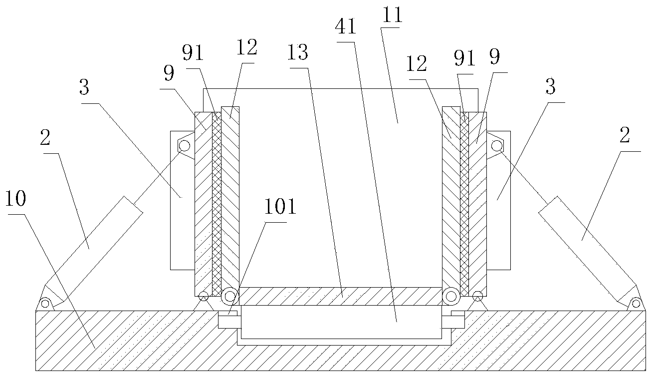
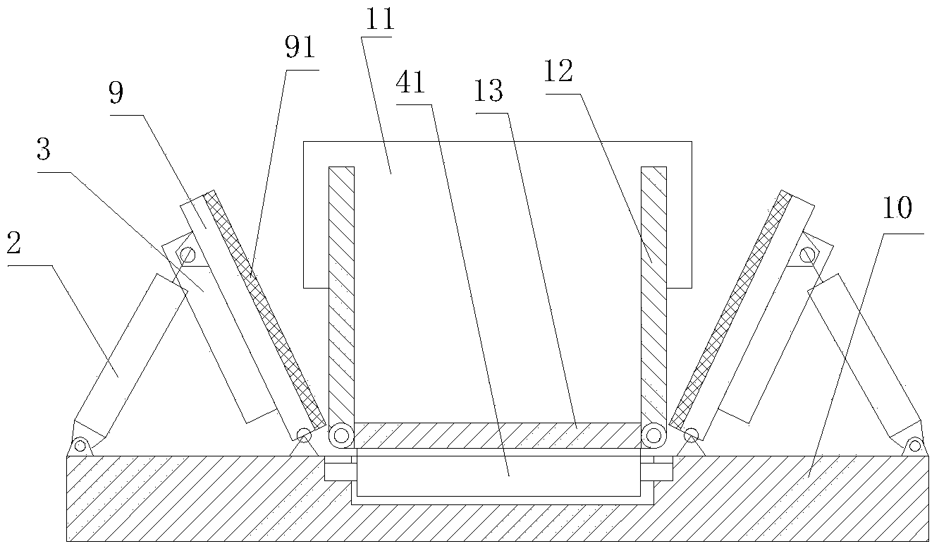
[0015] Embodiment 1: refer to Figure 1-7 . A prefabricated beam slab molding die, comprising a bottom plate 10, a vibrating plate and a formwork 1, the formwork 1 is composed of a base plate 13 placed on the bottom plate 10, two sets of side formworks 12 and two sets of end formworks 11, two sets of The side templates 12 are respectively connected to the top of the base plate 13 and are arranged oppositely front and back. Two groups of end templates 11 are connected to the left and right ends of the two groups of side templates 12 above the base plate 13. The vibration plates 9 are respectively located outside the two groups of side templates 12, and Its lower end is respectively hinged with the bottom plate 10, and a number of attached high-frequency vibrators 3 are respectively provided on the outer sides of the vibration plates 9 on the front and rear sides, and a rubber pad 91 is provided on the inner wall between the vibration plate 9 and two groups of side templates 12,...


PUM


Abstract

The invention relates to a forming mold for a precast beam plate. The forming mold for the precast beam plate comprises a bottom plate and a mold frame, wherein the mold frame comprises a base plate arranged on the bottom plate, two groups of side templates and two groups of end templates; the two groups of side templates are connected to the upside of the base plate respectively, and the front sides and the back sides of the two groups of the side templates are opposite to each other; the two groups of the end templates are connected to the left and right ends of the two groups of the side templates above the base plate; vibrating plates are located at the outer sides of the two groups of the side templates respectively while the lower ends of the vibrating plates are hinged to the bottom plate respectively; attachable high-frequency vibrating tampers are arranged on the outer sides of the vibrating plates at the front and back sides respectively; a rubber pad is arranged on an inner wall between the vibrating plates and the two groups of the side templates; multiple cylinders are arranged at the outer sides of the vibrating plates at the two sides respectively; a piston rod end of each cylinder is hinged to the outer walls of the vibrating plates at the two sides; the cylinder body end of each cylinder is hinged to the bottom plate.

Description

technical field [0001] The invention relates to a mold for forming a prefabricated beam plate. Background technique [0002] In the production process of traditional bridge prefabricated beams and slabs, the steel molds used in the vertical formwork range from more than 100 kilograms to four to five tons. Manual assembly is very laborious. Generally, gantry cranes and manual methods are used to assemble the formwork, but the efficiency It is still not high, and the speed is very slow. According to the statistics of this construction technology, a bridge girder slab production line with an annual production capacity of 5,000 cubic meters of concrete, with the assistance of gantry cranes, needs to be equipped with 8 manual assembly formworks, and only 5 can be assembled in a day. Set of templates. After assembling the formwork, it is necessary to manually measure the size, adjust the angle, and level it each time. Therefore, it is impossible to guarantee that the formwork ass...

Claims


Application Information

Patent Timeline
IPC IPC(8): B28B7/22B28B7/26
CPCB28B7/0029
Inventor 王学平
Owner 浙江鼎盛交通建设有限公司
Learn More