Push wheel mechanism of spreading machine

A paver and push-push technology, which is applied to roads, road repairs, roads, etc., can solve the problems of insufficient push wheel distance, damage to the paver front wall, hood, and large impact load of the paver. To achieve universality and improve the quality of pavement construction

Inactive Publication Date: 2014-01-29
XUZHOU CAMEL HEAVY ENG TECH
View PDF0 Cites 0 Cited by
  • Summary
  • Abstract
  • Description
  • Claims
  • Application Information

AI Technical Summary

Problems solved by technology

[0006] 1. Due to the rigid connection between the bearing support and the push frame, and between the push frame and the frame beam, during the paving operation, when the material transport vehicle dumps the material to the hopper receiving system, the material will not be transported. The car will generate a large inertial force. The moment the push wheel mechanism contacts the material transport vehicle, the impact load of the material transport vehicle on the paver is very large. Backward movement, which will seriously affect the operation effect of the paver;
[0007] 2. Due to the various types of material trucks currently used in construction, the distance from the rear wheel to the rear compartment plate is different, and some paver models are small and short, sometimes the distance that the push wheels protrude from the frame is not enough. Occurs that the rear compartment board of the material transport truck damages the front wall board and machine cover of the paver during unloading, and damages the paver

Method used


Image

  • Push wheel mechanism of spreading machine
  • Push wheel mechanism of spreading machine

Examples


Embodiment Construction

[0021] The present invention will be further described below in conjunction with the accompanying drawings.

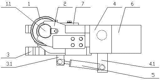
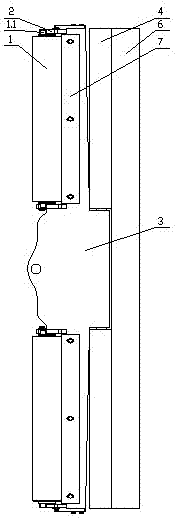
[0022] like figure 1 As shown, the push wheel mechanism of the paver includes a push wheel 1, a support 2, a push frame 3, a front counterweight 4 and a hydraulic cylinder 5 (the following description takes the forward direction of the paver as the front).

[0023] The push wheel 1 is set in two pieces, and the two ends are respectively provided with rollers 1.1 with bearings installed, and the rollers 1.1 are fixedly connected to the support 2.

[0024] The support 2 is set to four pieces, which are symmetrically arranged on the push frame 3 in pairs.

[0025] The width of the push frame 3 is the same as that of the crossbeam 6 of the paver frame. The front center of the push frame 3 is provided with a traction hole, and the rear part is hingedly connected with the front counterweight 4 through hinge pins. With hinged seat I 3.1.

[0026] The front counterweight 4 ...


PUM


Abstract

The invention discloses a push wheel mechanism of a spreading machine. The push wheel mechanism comprises push wheels (1), supporting seats (2), a rear push frame (3), a front balance weight (4) and a hydraulic cylinder (5), wherein the number of the push wheels is two, a rolling shaft (1.1) is arranged at each of two ends of each push wheel respectively and is fixedly connected with the supporting seats; the number of the supporting seats is four, and the four supporting seats are fixedly arranged on the rear push frame in two-two symmetry; the width of the rear push frame is equal to that of a frame cross beam (6), a traction hole is formed in the center of the front part of the rear push frame, the rear part of the rear push frame is in hinged connection with the front balance weight, and a hinging seat I (3.1) is arranged on the bottom surface of the rear push frame; the front balance weight is fixedly connected with the frame cross beam, and a hinging seat II (4.1) is arranged on the bottom surface of the front balance weight; the two ends of the hydraulic cylinder are in hinged connection with the hinging seat I and the hinging seat II respectively, and the hydraulic cylinder is connected with a hydraulic oil pump through a hydraulic pipeline and a valve bank. The push wheel mechanism of the spreading machine can relieve and absorb impact load of a material mover to the spreading machine, can adapt to the sizes of material movers of different model numbers, and can prevent a front panel of the spreading machine from being damaged.

Description

technical field [0001] The invention relates to a paver, in particular to a paver push wheel mechanism, and belongs to the technical field of paver. Background technique [0002] The paver is a large-scale engineering machinery integrating electromechanical hydraulics, which is mainly used for the uniform paving of various materials on the base and surface of the expressway. [0003] The mechanical system of the paver is mainly composed of the frame system, the walking system, the hopper receiving system, the scraper conveying system, the auger material distribution system, the leveling system, and the ironing device. The function of the hopper receiving system is Receive the mixed material unloaded by the transport truck and store it temporarily. There is generally a push wheel mechanism at the front and bottom of the hopper. paving for long distances. [0004] The push wheel mechanism of the known paver generally includes a push wheel, a support and a push frame. The pus...

Claims


Application Information

Patent Timeline
IPC IPC(8): E01C19/12
Inventor 杨玉峰韩毅黄建革
Owner XUZHOU CAMEL HEAVY ENG TECH
Why Eureka
Try Eureka