Vibrating machine
A vibrating machine and vibrating rod technology, applied in construction, building structure, processing of building materials, etc., can solve the problems of high labor intensity of construction workers, poor working environment, affecting the construction quality of concrete projects, etc.
Inactive Publication Date: 2014-01-29
SHAANXI SHENGMAI PETROLEUM
View PDF0 Cites 3 Cited by
- Summary
- Abstract
- Description
- Claims
- Application Information
AI Technical Summary
Problems solved by technology
The labor intensity of construction workers is high, the working environment is poor, and their health is endangered, which affects the overall construction quality of concrete projects
Method used
View moreImage
Smart ImageViewing Examples

Examples
Embodiment 1
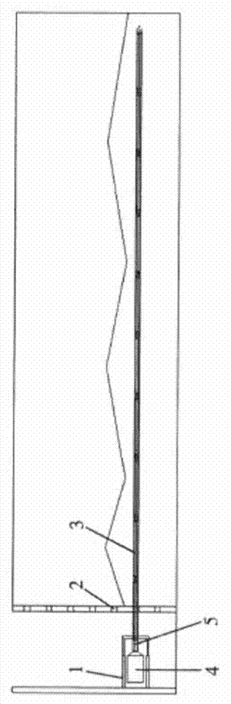
[0010] The vibrating machine of the present invention comprises a frame on which a support plate is arranged, wherein a hydraulic cylinder 1 is fixedly arranged on the frame, and a motor 4 is arranged in the hydraulic cylinder 1, and the motor 4 is connected to the vibrating rod through a universal connector 5 3 connected. Several vibrator insertion holes 2 are provided on the support plate, and the vibrating rod 3 passes through the vibrator insertion holes 2 .
Login to View More PUM
 Abstract
The invention relates to a vibrating machine which comprises a frame. A hydraulic cylinder is fixedly arranged on the frame, and a motor is arranged in the hydraulic cylinder and connected with a vibrating rod. By the vibrating machine, the above various defects can be effectively overcome, labor intensity is greatly lowered, working environment is improved, and a people-oriented design concept is reflected.
Description
technical field [0001] The invention relates to a vibrating device. Background technique [0002] For a long time, the compaction of concrete has been achieved by operators holding a vibrator and vibrating on the surface of the concrete. The labor intensity of construction workers is high, the working environment is poor, and their health is endangered, which affects the overall construction quality of concrete projects. Contents of the invention [0003] The present invention aims to provide an automatic vibrator. [0004] The vibrating machine of the present invention includes a frame, wherein a hydraulic cylinder is fixedly arranged on the frame, and an electric motor is arranged inside the hydraulic cylinder, and the electric motor is connected with the vibrating rod. [0005] Preferably, the motor is connected to the vibrating rod through a universal connector. [0006] Or preferably, a support plate is provided on the frame, and several vibrator insertion holes ar...
Claims
Login to View More Application Information
Patent Timeline
 IPC IPC(8): E04G21/08
Inventor 王耀斌
Owner SHAANXI SHENGMAI PETROLEUM