Fixing structure of LED light source substrate and installing method

A technology of LED light source and LED substrate, which is applied in the field of LED lighting, can solve problems such as large contact thermal resistance, time-consuming, and potential safety hazards, and achieve the effects of increasing the heat conduction area, improving heat conduction performance, and improving heat conduction effect

Inactive Publication Date: 2014-01-29
HUBEI AISAN PHOTOELECTRIC
View PDF3 Cites 0 Cited by
  • Summary
  • Abstract
  • Description
  • Claims
  • Application Information

AI Technical Summary

Problems solved by technology

If it is fixed with screws, it is not only time-consuming to produce, but also easy to loosen, so there is a potential safety hazard, and the heat conduction effect is not ideal, because there must be an air gap in the middle, resulting in a large contact thermal resistance
If you use thermal paste, etc., on the one hand, the thermal paste with better thermal conductivity is more expensive, and the low thermal conductivity cannot achieve good thermal conductivity. On the other hand, it is quite time-consuming to apply this paste.
These shortcomings limit the popularization and application of LED lighting technology.

Method used


Image

  • Fixing structure of LED light source substrate and installing method
  • Fixing structure of LED light source substrate and installing method
  • Fixing structure of LED light source substrate and installing method

Examples


Embodiment Construction

[0028] The following is a non-limiting description of the LED light source substrate fixing structure and installation and use method of the present invention in conjunction with the accompanying drawings, in order to facilitate the public to better understand the technical content.

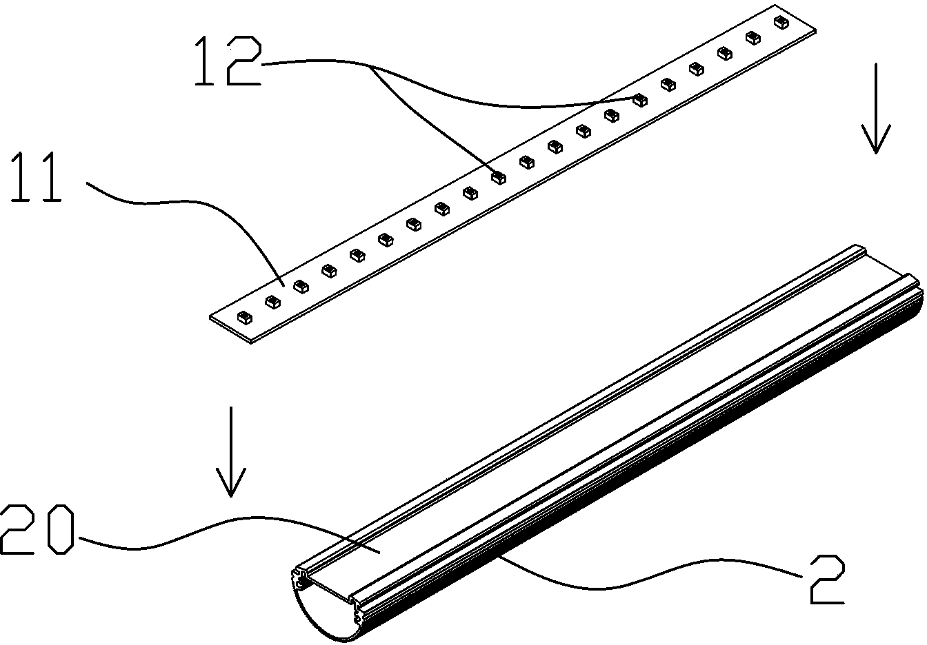
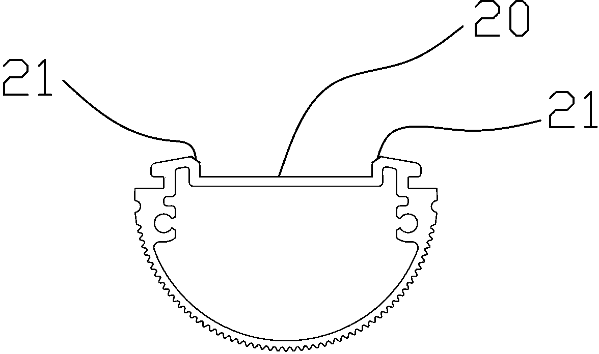
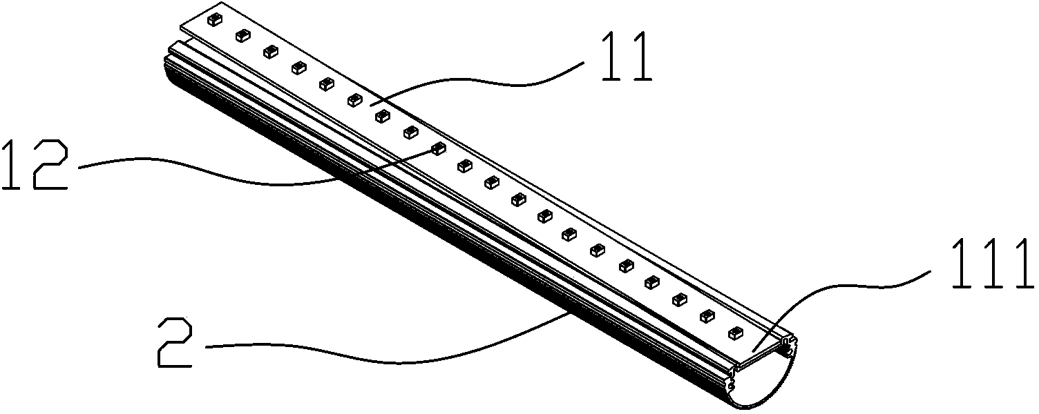
[0029] like Figure 1-6 , the LED light source substrate fixing structure of the present invention includes an LED substrate and a heat dissipation profile, wherein the LED substrate includes a substrate 11 and a plurality of LEDs 12 arranged on the substrate 11, and the heat dissipation profile 2 is a hollow columnar structure with the same length as the substrate 11 One side is provided with a slot 20 for accommodating the substrate 11 , and the two sides of the slot 20 are respectively provided with slopes 21 inclined inwardly and downwardly. In this embodiment, the substrate 11 and the heat dissipation profile 2 are made of aluminum or aluminum alloy, which has better heat conduction effect. ...


PUM


Abstract

The invention provides a fixing structure of an LED light source substrate and an installing method of the fixing structure of the LED light source substrate. The fixing structure of the LED light source substrate comprises the LED substrate and a heat dissipation sectional bar, wherein the LED substrate comprises a substrate body and LEDs arranged on the substrate body, the heat dissipation sectional bar is of a hollow columnar structure, the length of the heat dissipation sectional bar is equal to that of the substrate body, a clamping groove used for containing the substrate body is formed in one side of the heat dissipation sectional bar, and slopes which incline in an inwards-downward mode are arranged on the two side edges of the clamping groove respectively. Further, the clamping groove and the substrate body are in interference fit, and the width of the clamping groove is smaller than that of the substrate body. Due to the design, the substrate body can be more closely embedded into the heat dissipation sectional bar, and the optimal heat dissipation effect is achieved. Due to the fixing mode of the LED fluorescent tube light source substrate, assembly is carried out with the help of machines, the assembly is easier, the production cost is greatly reduced, the reliability is high, and the heat conduction performance can be improved.

Description

[0001] technical field [0002] The invention relates to a fixing structure of an aluminum substrate of a light source, in particular to a fixing structure of an aluminum substrate of an LED fluorescent tube light source and a heat-dissipating aluminum profile and an installation method thereof, belonging to the technical field of LED lighting. [0003] Background technique [0004] At present, in the LED industry, when manufacturing LED fluorescent tubes, the common methods for fixing the aluminum substrate of the light source to the heat-dissipating aluminum alloy shell are mostly screw fixing, coating of heat-conducting adhesive, and pasting of heat-conducting double-sided tape. If it is fixed with screws, it will not only be time-consuming to produce, but also easy to loosen, so there is a safety hazard, and the heat conduction effect is not ideal, because there must be an air gap in the middle, resulting in a large contact thermal resistance. For example, applying ther...

Claims


Application Information

Patent Timeline
Patent Type & Authority Applications(China)
IPC IPC(8): F21V19/00F21V29/00F21Y101/02F21V29/85F21Y103/10F21Y115/10
Inventor 熊念春
Owner HUBEI AISAN PHOTOELECTRIC
Why Eureka
Try Eureka