
Temperature and humidity joint control system of capillary radiation air conditioner

A technology of radiant air conditioning and temperature-humidity joint control, applied in heating and ventilation control systems, heating and ventilation safety systems, space heating and ventilation, etc. Uniform distribution and good energy saving effect

Active Publication Date: 2014-01-29
上海誉德动力技术集团股份有限公司 +1
View PDF11 Cites 1 Cited by
  • Summary
  • Abstract
  • Description
  • Claims
  • Application Information

AI Technical Summary

Problems solved by technology

[0004] Therefore, it is proposed to solve the problem of easy condensation when using radiant air conditioners in high temperature and high humidity areas in summer

Method used


Image

  • Temperature and humidity joint control system of capillary radiation air conditioner
  • Temperature and humidity joint control system of capillary radiation air conditioner
  • Temperature and humidity joint control system of capillary radiation air conditioner

Examples


Embodiment

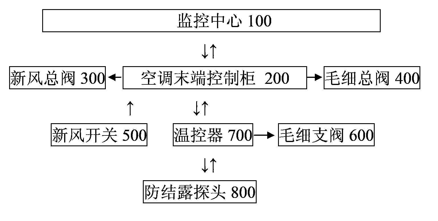
[0040] figure 1 It is a functional block diagram of the present invention.

[0041] The temperature and humidity joint control system of the capillary radiation air conditioner includes: monitoring center 100, air conditioner terminal control cabinet (APC) 200, fresh air main valve 300, capillary main valve 400, fresh air switch 500, capillary branch valve 600, thermostat 700, anti-condensation Dew probe 800.

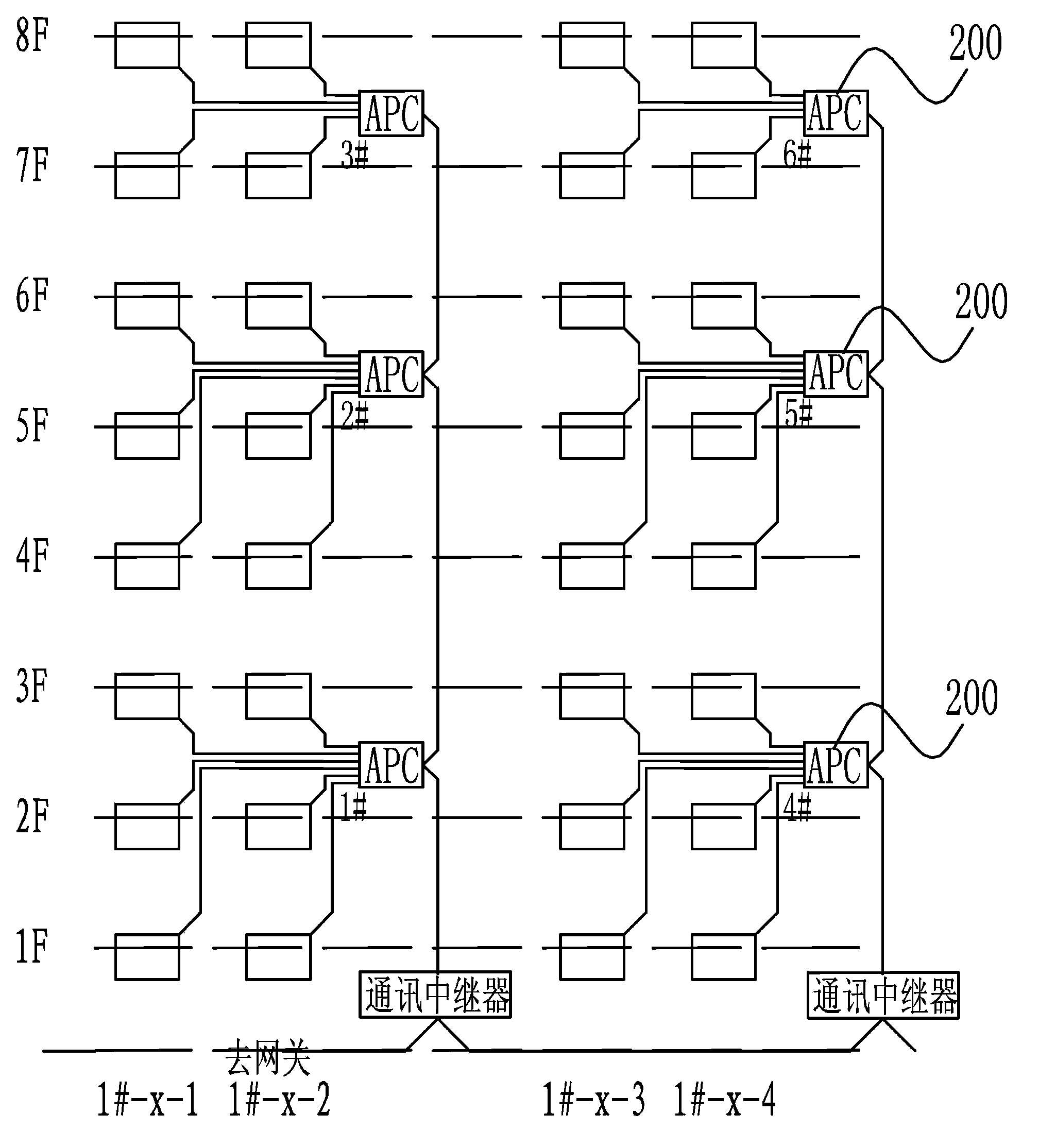
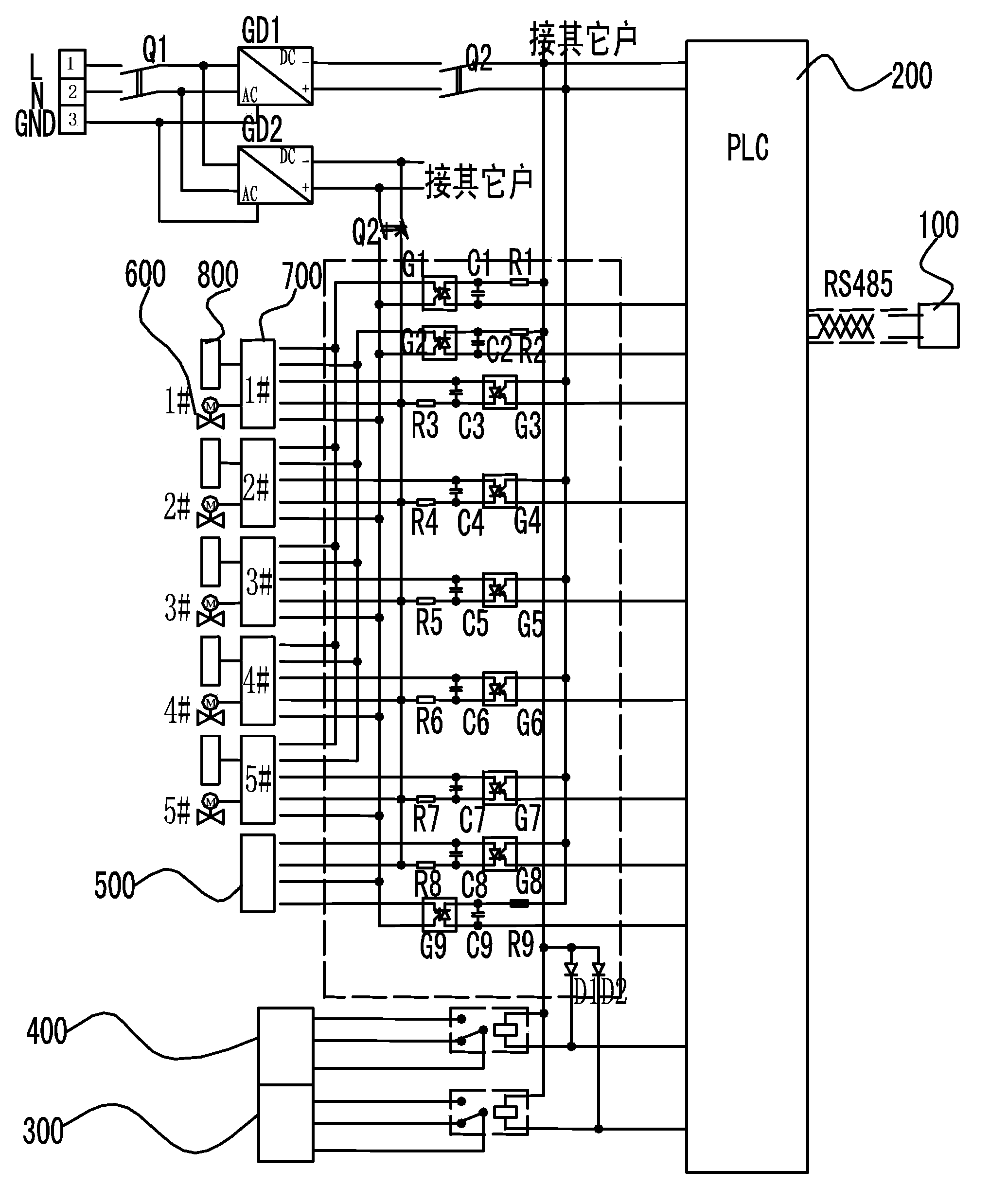
[0042] figure 2 It is the physical layout system diagram of the present invention, image 3 It is a working system diagram of the present invention. Such as figure 2 and image 3 As shown, the monitoring center 100 adopts a PC.

[0043] The air conditioner terminal control cabinet (APC) 200 is the most important equipment in this system. Its core is a programmable controller PLC, and the programmable controller is responsible for connecting with the host computer—the PC in the monitoring center 100, and receiving the working mode of the air-conditioning system ...


PUM


Abstract

The invention discloses a temperature and humidity joint control system of a capillary radiation air conditioner. The temperature and humidity joint control system comprises an air conditioner tail end control cabinet (200), a fresh air master valve (300), a capillary master valve (400), a fresh air switch (500), a capillary branch valve (600), a temperature controller (700) and an anti-condensation probe (800) in a connecting mode. The air conditioner tail end control cabinet (200) receives a working mode signal of an air conditioner room from a monitoring center (100). The temperature controller (700) receives the working mode signal transmitted by the air conditioner tail end control cabinet (200) and is further connected with the capillary branch valve (600) and the anti-condensation probe (800) measuring relative temperature and humidity. The temperature and humidity joint control system is used for solving the problem that the radiation air conditioner is prone to condensation when used for summer high-temperature high-humidity areas.

Description

technical field [0001] The invention relates to a control system of an air conditioner, in particular to a temperature-humidity joint control system of a capillary radiation air conditioner, and belongs to the technical field of air conditioners. Background technique [0002] In the early radiant air-conditioning system, doors and windows were forbidden to be opened in summer, which limited the freedom of use of residents. [0003] However, for areas with high relative humidity in summer, the use of radiant air conditioning systems in summer needs to solve the problem of preventing condensation on the ceiling or walls. Especially when the doors and windows are opened, the external hot and humid air enters and contacts with the radiant cold surface, which is most likely to cause condensation. [0004] Therefore, it is proposed that it is necessary to solve the problem of easy condensation when radiant air conditioners are used in high-temperature and high-humidity areas in s...

Claims


Application Information

Patent Timeline
IPC IPC(8): F24F11/02
Inventor 黄翔朱扬刘仁任泽平华嘉青
Owner 上海誉德动力技术集团股份有限公司
Learn More