Method for achieving self-defining test function sequence in a microwave measurement apparatus

A technology of testing functions and implementation methods, applied in the direction of instruments, measuring electronics, measuring devices, etc., can solve problems that are not conducive to the development of instrument application layers, system software is not easy to share, and inconvenient to use, so as to improve testing efficiency and standardize testing Process and test parameters, the effect of convenient development

Active Publication Date: 2014-01-29
CHINA ELECTRONIS TECH INSTR CO LTD
View PDF6 Cites 2 Cited by
  • Summary
  • Abstract
  • Description
  • Claims
  • Application Information

AI Technical Summary

Problems solved by technology

[0003] Disadvantages of the existing technology: the use of general-purpose microwave testing instruments to build a system requires an external control computer, which is large in size and high in cost, and it is very inconvenient to use, especially the instruments are increasingly developing towards miniaturization and multi-function. Users are required to have system building ability and system software programming ability
In addition, the system software is not easy to share, which is not conducive to the development of the instrument application layer

Method used


Image

  • Method for achieving self-defining test function sequence in a microwave measurement apparatus

Examples


Embodiment 1

[0025] The realization of the invention includes two parts: custom test function sequence editing function, custom test function sequence internal function realization,

[0026] 1. Realization of custom test function sequence editing function

[0027] In the command file selection dialog box of a custom menu key setting, select or input the command file corresponding to the custom key, and replace the string of "custom menu key 1" with the file name of the command file minus the extension. In this way, the custom test function sequence is given to the custom menu 1, and the custom test function can be executed by clicking this menu.

[0028] 2. Internal function implementation of custom test function sequence

[0029] The internal protocol format, storage format and keyword design of the command file:

[0030] Use the SCPI program-controlled instructions in the test instrument to create a command file. The syntax format follows the standard SCPI (Standard Command Set for Pro...

Embodiment 2

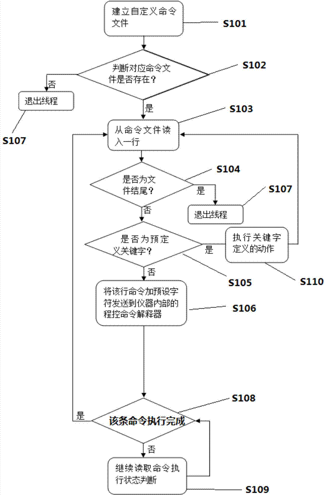
[0064] On the basis of the above embodiments, further, a method for realizing a self-defined test function sequence in a microwave measuring instrument is provided, which includes the following steps:

[0065] Step S101: Create a custom file;

[0066] Step S102: determine whether the corresponding command file exists, if yes, enter step S103; otherwise, enter step S111;

[0067] Step S103: read one line from the command file;

[0068] Step S104: judge whether it is the end of the file, if yes, go to step S107; otherwise, go to step S105;

[0069] Step S105: judge whether it is a predefined keyword, if yes then enter step S110; if otherwise enter step S106;

[0070] Step S106: After sending the line command plus preset characters to the program-controlled command interpreter inside the instrument, enter step S108;

[0071] Step S107: Exit the thread;

[0072] Step S108: Judging whether the execution of the command is completed, if yes, go to step S103; otherwise, go to step...


PUM


Abstract

The invention provides a method for achieving a self-defining test function sequence in a microwave measurement apparatus. The method comprises the following steps: S101, establishing a self-defined command file; S102, judging whether a corresponding command file exists; S103, reading one line from the command file; S104, judging whether a command is the file end; S105, judging whether the command is a key word which is defined in advance; S106, adding a preset character to the command, and sending the command to a program command interpreter; S108, judging whether the command is executed; S109, continuing to read the command executing state for judgment; S110, entering S103 after executing the key word definition. By the adoption of the scheme, test work of the user is greatly facilitated, and test efficiency is improved. Particularly, compared with system establishment, the method is conveniently used by a production line, and meanwhile test flow and a test parameter can be regulated, setting of a test stays the same, and measurement results can be conveniently compared.

Description

technical field [0001] The invention belongs to the technical field of microwave measurement, and in particular relates to a method for realizing a self-defined test function sequence in a microwave measuring instrument. Background technique [0002] The devices or equipment produced in the production line need general testing equipment to test some of their indicators to check whether the quality standards are met. General-purpose testing instruments require users to click one by one to complete the test. For this type of production, the test efficiency affects the production efficiency of the production line. At present, most general-purpose test instruments require specialized programmers and designers to complete personalized test work. Therefore, large-scale production lines mostly purchase general-purpose test instruments and computers, and build special systems through instrument program-controlled commands to realize customized test work. However, the cost of custom...

Claims


Application Information

Patent Timeline
IPC IPC(8): G01R31/00G01R23/16
Inventor 王保锐刘丹陈安军赵永志
Owner CHINA ELECTRONIS TECH INSTR CO LTD
Why Eureka
Try Eureka