Mutual inductor on-site inspection tester

An on-site inspection and transformer technology, applied in the field of inspection instruments, can solve the problems of inaccurate measurement, limited function, inability to accurately determine the failure time and development trend, and achieve the effect of increasing safety, convenience, and continuous testing.

Inactive Publication Date: 2014-01-29
STATE GRID CORP OF CHINA +1
View PDF3 Cites 6 Cited by
  • Summary
  • Abstract
  • Description
  • Claims
  • Application Information

AI Technical Summary

Problems solved by technology

The main reason for this is that when using the traditional method to verify the transformer, it is necessary to cut off the power of the equipment once. In the case of no obvious appearance damage or abnormal power, the user is unwilling to interrupt the power supply for the verification of the error; moreover, the on-site verification of the transformer A lot of equipment is required, safety measures and work processes are complicated, and it is not realistic to require thousands of sets of high-voltage customers to perform power-off cycle verification like electric energy meters
However, the metering device is a whole composed of transformers, electric energy meters, and secondary circuits. If there is a problem in any part, it cannot be accurately measured. Because the transformer does not have a dynamic and stable on-site detection method like the electric energy meter, we It is impossible to know the error change trend of the transformer in the past 10 years, and it is impossible to timely and accurately discover some hidden faults inside it that have gradually developed due to long-term accumulation, such as long-term harmonics or resonant overvoltages that make TV error characteristics Deterioration, the thermal effect of various losses destroys the magnetic permeability of the TV iron core, slight damage to the coil during installation, long-term operation develops into interlayer or interturn short circuit, etc.
Even if the on-site verification is carried out after 10 years, the role played is very limited. The qualified ones are still qualified, and the unqualified ones cannot effectively make up for the lost power because they cannot accurately determine the time and development trend of the fault.
Therefore, for the current operation and maintenance of transformers, we can only wait for a fault to occur or the power is abnormal before processing. This is a completely passive and primitive way that cannot meet the requirements of forward-looking and preventive

Method used


Image

  • Mutual inductor on-site inspection tester
  • Mutual inductor on-site inspection tester
  • Mutual inductor on-site inspection tester

Examples


Embodiment Construction

[0030] The present invention will now be described in further detail in conjunction with the accompanying drawings and preferred embodiments. These drawings are all simplified schematic diagrams, which only illustrate the basic structure of the present invention in a schematic manner, so they only show the configurations related to the present invention.

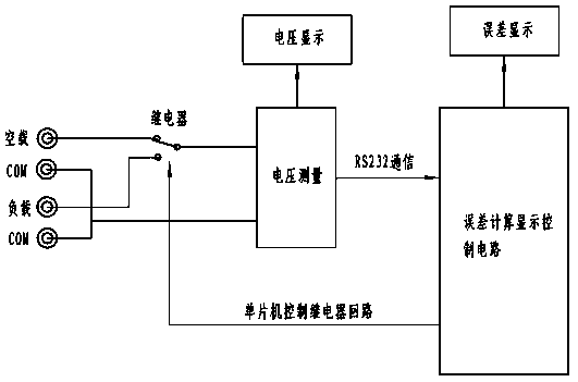
[0031] Such as figure 1 The transformer on-site inspection instrument shown includes a voltage measurement circuit, an error calculation display control circuit, a voltage display circuit, a relay, and an error display circuit; the measurement accuracy of voltage measurement is ±0.5%, with 5 effective digits and two digits after the decimal point. Voltage measuring meter with a measuring range of 150V. The meter is responsible for testing and displaying the voltage value, and transmits the test voltage data to the error calculation and display control circuit through 232 communication to calculate the voltage error. The me...


PUM


Abstract

The invention relates to a mutual inductor on-site inspection tester which comprises a voltage measuring circuit, an error computing displaying control circuit, a voltage displaying circuit, a relay and an error displaying circuit. The voltages displaying circuit is connected with the output end of the voltage measuring circuit. The error displaying circuit is connected with the output end of the error computing displaying control circuit. One end of the relay is controlled by the error computing displaying control circuit. The other end of the relay is connected with a load and a mutual inductor. The voltage measuring circuit detects the secondary voltage value of the mutual inductor, detected data are transmitted to the error computing displaying control circuit through a communication bus, the error computing displaying control circuit carries out voltage error computing, and then the data are displayed through the voltage displaying circuit and the error displaying circuit. The mutual inductor on-site inspection tester can reflect the operation quality of a TV, one-time power failure is of no need, operation on site is easy, safety measures are not higher than the requirement of on-site meter correction, and meter correction can be carried out at the same time.

Description

technical field [0001] The invention relates to the field of electrical equipment, in particular to an inspection instrument for on-site inspection of electric energy metering equipment in a power system. Background technique [0002] On-site periodic calibration is an important technical means to ensure the stable and reliable operation of the metering device. However, the main objects of the current on-site calibration are the electric energy meter and the secondary circuit. The transformer is basically not involved, and the regulations only stipulate: Device, on-site inspection every 10 years. The main reason for this is that when using the traditional method to verify the transformer, it is necessary to cut off the power of the equipment once. In the case of no obvious appearance damage or abnormal power, the user is unwilling to interrupt the power supply for the verification of the error; moreover, the on-site verification of the transformer A lot of equipment is requ...

Claims


Application Information

Patent Timeline
Patent Type & Authority Applications(China)
IPC IPC(8): G01R35/02
Inventor 李峰彭斌蒋辉张曦麻海峰刘辉廖勇石秀华向焱
Owner STATE GRID CORP OF CHINA
Why Eureka
Try Eureka