A shielded motor stator cavity cooling structure

A shielded motor and cooling structure technology, applied in cooling/ventilation devices, electrical components, electromechanical devices, etc., can solve the problems of shielded motor failure, unsatisfactory heat dissipation effect, poor air heat transfer effect, etc., to ensure safe and stable operation, The effect of avoiding the failure of the shielded motor and meeting the sealing requirements

Active Publication Date: 2016-07-06
NUCLEAR POWER INSTITUTE OF CHINA
View PDF6 Cites 0 Cited by
  • Summary
  • Abstract
  • Description
  • Claims
  • Application Information

AI Technical Summary

Problems solved by technology

However, after adopting such a closed structure of the stator cavity, it is unfavorable for the heat dissipation of the motor stator. Therefore, in order to cool the motor stator cavity that is closed and has a poor heat dissipation effect, a jacket layer is usually set on the outer wall of the motor stator cylinder, and Use secondary cooling water to transfer heat through the outer wall of the motor stator cylinder to remove heat from the inner cavity of the stator for cooling
[0004] However, the heat dissipation effect of this method of secondary cooling water cooling on the outer wall of the motor cylinder is not ideal, because the heat transfer effect of the air in the cavity at the two ends of the stator inner cavity is relatively poor, resulting in the inner cavity at the two ends of the motor stator. The winding coil is in a relatively high temperature environment, especially in the case of power failure, pump shutdown and secondary cooling water loss, the heat sealed in the inner cavity of the motor stator cannot be exported, which may easily cause the temperature of the inner cavity of the motor stator to exceed the allowable insulation temperature, eventually causing the shielded motor to fail

Method used


Image

  • A shielded motor stator cavity cooling structure
  • A shielded motor stator cavity cooling structure
  • A shielded motor stator cavity cooling structure

Examples


Embodiment 1

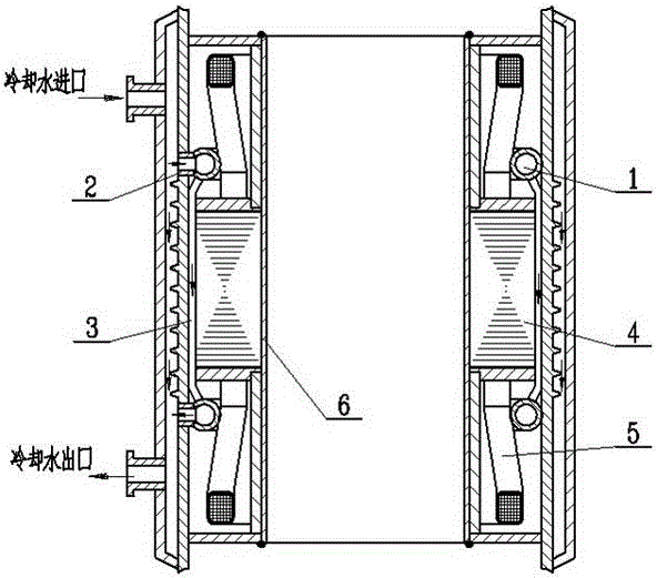
[0025] Such as figure 1 As shown, in the prior art, in order to solve the heat dissipation problem of the sealed inner cavity of the stator, the method of setting a cooling water jacket on the outer wall of the motor stator cylinder is mainly adopted, and the heat transfer between the secondary cooling water and the outer wall of the motor stator cylinder is used. Take away the heat of the inner cavity of the stator for cooling. In view of the poor effect of this cooling method, on the basis of this solution, this embodiment provides a shielded motor stator cavity cooling structure, which is provided with cooling water pipes 1 in the airtight cavity at both ends of the shielded motor stator core 4 , the cooling water pipe 1 communicates with the cooling water jacket on the outer wall of the shielded motor stator cylinder. In this embodiment, a cooling structure is provided in the motor stator barrel to form a cooling water inflow and outflow circuit, which can effectively tak...

Embodiment 2

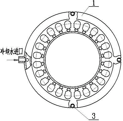
[0027] Such as figure 1 with figure 2As shown, this embodiment has made further improvements on the basis of Embodiment 1. The number of cooling water pipes 1 in this embodiment is 2, and one is respectively arranged in the airtight cavity at both ends of the stator core 4 of the shielded motor. The water pipe 1 is annularly arranged in the airtight cavity at both ends of the stator core 4 of the shielded motor. The pipe wall of the cooling water jacket is sealed and connected to prevent the cooling water from entering the closed stator cavity. Wherein the cross section of the cooling water pipe 1 is circular. In practical application, if the space in the airtight cavity is large, multiple cooling water pipes 1 can be arranged in the airtight cavity at both ends to enhance the effect of heat dissipation and cooling; the cross section of the cooling water pipe 1 can also be any other regular or irregular Shapes, such as regular hexagons, regular octagons, trapezoids, etc. ...

Embodiment 3

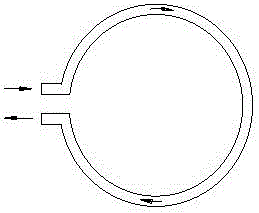
[0029] Such as image 3 As shown, on the basis of Embodiment 2, there are two connecting pipes 2 in this embodiment, which are located on the same side of the annular surface of the cooling water pipe 1 . The cooling water pipes 1 at both ends of the stator core 4 respectively form a secondary cooling water inflow and outflow circuit. Since the two connecting pipes 2 are located on the same side of the annulus of the cooling water pipe 1, the secondary cooling water enters the cooling water pipe 1 through one of the connecting pipes 2, and flows through the closed cavity along the cooling water pipe 1 for a circle and then flows from the other A connecting pipe 2 flows out and flows back to the cooling water jacket.


PUM


Abstract

The invention discloses a cooling structure for a stator cavity of a shielded motor, which comprises a cooling water pipe (1) arranged in a closed cavity at both ends of a stator core (4) of the shielded motor, and the cooling water pipe (1) is connected with the stator barrel of the shielded motor The cooling water jacket on the outer wall is connected. The invention can effectively take out the heat accumulated in the airtight cavities at both ends of the motor stator, improve the temperature distribution of the inner cavity of the motor stator, and can also use the motor stator cooling water clamp under the condition of power failure, pump shutdown or secondary cooling water loss. The temperature difference between the sleeve and the inner cavity of the stator produces a natural circulation of the fluid, thereby taking away part of the heat in the inner cavity of the stator, avoiding the failure of the shielded motor due to the temperature of the inner cavity of the motor stator exceeding the allowable temperature of the insulation, and improving the reliability of the stator winding coil of the shielded motor To ensure the safe and stable operation of nuclear energy installations.

Description

technical field [0001] The invention relates to the technical field of shielded motors, in particular to a cooling structure for a stator cavity of a shielded motor. Background technique [0002] In the field of nuclear energy technology, the high-temperature and high-pressure fully-sealed canned pump of the nuclear energy device adopts a fully-sealed structure to withstand the high-temperature and high-pressure primary circuit medium, and its motor part and hydraulic components are connected as a whole. in the liquid inside. [0003] In order to avoid motor failure caused by the stator core and winding coils of the motor being in contact with the reactor coolant liquid, the thin-walled stainless steel shielding sleeve 6 is mainly installed into the inner wall of the motor stator core 4, and the two ends of the shielding sleeve 6 are sealed and welded. means to achieve hermetic isolation. However, after adopting such a closed structure of the stator cavity, it is unfavorab...

Claims


Application Information

Patent Timeline
Patent Type & Authority Patents(China)
IPC IPC(8): H02K9/19
Inventor 邓礼平刘立志
Owner NUCLEAR POWER INSTITUTE OF CHINA
Why Eureka
Try Eureka