
Implant comprising a non-woven fabric

A technology of non-woven fabrics and implants, applied in textiles and papermaking, non-woven fabrics, electrospinning, etc., can solve problems such as not easy attachment

Active Publication Date: 2014-01-29
PHENOX
View PDF12 Cites 13 Cited by
  • Summary
  • Abstract
  • Description
  • Claims
  • Application Information

AI Technical Summary

Problems solved by technology

However, this type of membranes has the disadvantage that they are not easily attached to the stent carrying them, but are essentially mechanically held at the vessel wall by the expanding stent

Method used


Image

  • Implant comprising a non-woven fabric
  • Implant comprising a non-woven fabric
  • Implant comprising a non-woven fabric

Examples


Embodiment Construction

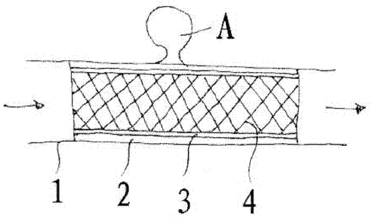
[0049] figure 1 Shows a membrane implant of the invention arranged in a blood vessel 1, the membrane of the implant has a spongy outer layer 2 in contact with the vessel wall, more or less membranes intended to prevent blood passing through the vessel (direction of the arrow) through the membrane The supporting structure or frame of the less fluid-tight inner layer 3 and the stent 4 for pressing the membrane against the vessel wall 1 . For example, a membrane can be used to isolate a botryoidal aneurysm A from the circulating blood flow and in this way cause the aneurysm to become occluded. However, the stent is also capable of containing drugs via its spongy outer layer in view of eg exerting an anti-stenotic effect on the wall of the dilated vessel.

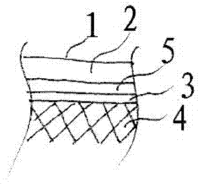
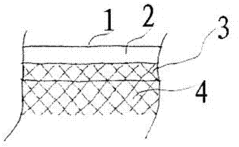
[0050] figure 2 Shows a section through the wall structure of a membrane implant according to the invention with a stent on the inside, an adjacent layer 3 designed to be substantially fluid-tight, a firm intermediate layer ...


PUM

PropertyMeasurementUnit
diameteraaaaaaaaaa

Abstract

The invention relates to a membrane implant for treating vascular malformations, for the endovascular implantation into the vessel to be treated, the membrane implant consisting of an expandable stent (4) and a membrane (2, 3, 5, 11) connected to the stent (4). Said membrane (2, 3, 5, 11) covers mesh of the stent (4) at least in a center region and is designed as a non-woven fabric that contains synthetic filaments. The membrane (2, 3, 5, 11) is integrally connected to the stent (4) and is porous in at least some sections.

Description

technical field [0001] The invention relates to a membrane implant for the treatment of vascular malformations, said implant consisting of an expandable stent and a membrane connected to said stent, wherein said membrane covers the mesh of said stent at least in the central region. The membrane implant is intended to be implanted intravascularly in the vascular system of the patient to be treated. Background technique [0002] For the treatment of vascular malformations, in particular of arteries, usually confined to a small area, a number of devices have been developed which apply purely or preferentially local effects of mechanical, thermal, chemical, electrical or pharmaceutical nature. These treatment methods are mainly based on endovascular techniques, by means of which the treatment device is guided via a catheter to the placement site and applied there. [0003] A common form of treatment, especially in conjunction with sclerotic narrowing of blood vessels, but also ...

Claims


Application Information

Patent Timeline
Patent Type & Authority Applications(China)
IPC IPC(8): D04H1/70D04H3/07A61F2/06A61F2/90A61L27/56D01D5/00A61F2/86A61F2/07A61F2/82A61F2/95
CPCA61L2300/41A61L31/146A61L31/16A61F2002/9505A61L2400/16A61F2/90A61L2300/416A61F2/86A61L31/10A61F2002/823A61F2/07D01F6/70D01D5/0084A61F2002/075C08L69/00A61B17/12113A61F2/06A61L27/14A61L27/54A61L27/56A61L31/022D01D5/0007D04H1/728
Inventor R·汉内斯H·蒙斯塔特
Owner PHENOX
Learn More