Anti-wear lubricating punch structure of power metallurgy die

A powder metallurgy, anti-wear technology, applied in the direction of manufacturing tools, presses, etc., can solve the problems of increasing equipment maintenance and replacement costs, and achieve the effects of preventing cold welding, reducing demoulding force, and protecting punches

Active Publication Date: 2014-02-05
GUANGDONG DONGMU NEW MATERIALS
View PDF11 Cites 0 Cited by
  • Summary
  • Abstract
  • Description
  • Claims
  • Application Information

AI Technical Summary

Problems solved by technology

In the process of actually producing flanges and other products, the proportion of punches scrapped due to breakage is very high, which increases the maintenance and replacement costs of equipment

Method used


Image

  • Anti-wear lubricating punch structure of power metallurgy die
  • Anti-wear lubricating punch structure of power metallurgy die
  • Anti-wear lubricating punch structure of power metallurgy die

Examples


Embodiment Construction

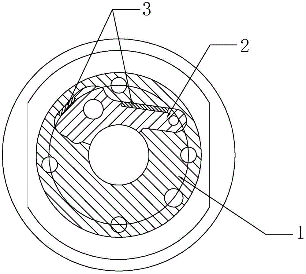
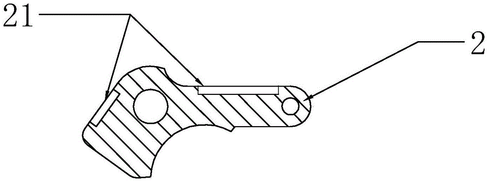
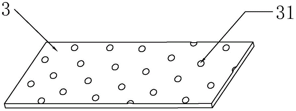
[0017] refer to Figure 1 to Figure 3 , an anti-wear lubricating punch structure of a powder metallurgy mold according to the present invention, comprising a first die punch 1, and a second die punch 2 fitted in the first die punch 1, the second die punch 2 The side is provided with a fixing groove 21, and a sheet-shaped lubricating bearing 3 is clamped in the fixing groove 21. The outer surface of the lubricating bearing 3 protrudes from the side of the second die punch 2 and is offset against the inner surface of the first die punch 1. Next, the outer surface of the lubricating bearing 3 is provided with a notch 31 for accommodating lubricating liquid such as butter. The outer surface of the lubricating bearing 3 is a working surface, which is slidingly matched with the inner surface of the first die punch 1 .

[0018] A plurality of notches 31 are provided on the outer surface of the lubricating bearing 3 .

[0019] The notches 31 are linearly and equidistantly arranged i...


PUM


Abstract

The invention discloses an anti-wear lubricating punch structure of a power metallurgy die. The anti-wear lubricating punch structure comprises a first punch and a second punch fitly inserted into the first punch. The side of the second punch is provided with a fixing channel, and a sheet lubricating bearing is locked in the fixing channel. The outer side of the lubricating bearing projects out of the side of the second punch and is abutted to the inner side of the first punch. The outside of the lubricating bearing is provided with a cavity used for accommodating lubricating liquid. The anti-wear lubricating punch structure has the advantages that the lubricating bearing is added between the punches of the power metallurgy die, lubricating liquids such as grease are added to the lubricating bearing, abrasion between the punches can be reduced, and friction between the punches during die stripping is reduced accordingly; through the addition of the lubricating bearing, cold welding during formation of the punches can be prevented, stripping force between the dies is reduced, and the punches are protected.

Description

technical field [0001] The invention relates to a punch structure of a powder metallurgy mold. Background technique [0002] For powder metallurgy molds with multi-down punch structure, especially when a certain punch has a non-circular structure, asymmetric side pressure will be generated when the product is formed. If the radial envelope of the punch is less than 180°, excessive side pressure will cause great friction between the punches, and even break the punch when demoulding. In the process of actually producing flanges and other products, the proportion of punches scrapped due to breaking is very high, which increases the maintenance and replacement costs of equipment. Contents of the invention [0003] In order to overcome the disadvantages of the prior art that the friction between the punches is large, the punches are easily broken when demoulding, and the scrap ratio is high, the invention provides an anti-wear and lubricating punch structure for a powder metal...

Claims


Application Information

Patent Timeline
IPC IPC(8): B30B15/02
Inventor 梁集标曾锦艳
Owner GUANGDONG DONGMU NEW MATERIALS
Why Eureka
Try Eureka