Electro-hydraulic composite braking system with electric braking assistant force and brake-by-wire function

A technology of electric braking and brake-by-wire

Active Publication Date: 2014-02-05
南京经纬达汽车科技有限公司
View PDF7 Cites 42 Cited by
  • Summary
  • Abstract
  • Description
  • Claims
  • Application Information

AI Technical Summary

Problems solved by technology

The brake-by-wire system overcomes two obvious deficiencies of the traditional power-assisted braking system: one is that it cannot conveniently implement active braking (the so-called "active braking" means that it can still be achieved when the brake pedal is not pressed down). braking of all or part of the wheels); second, as long as the driver depresses the brake pedal, the friction brake is involved in generating braking force
Although various types of brake-by-wire systems have many advantages as mentioned above, they also have some disad

Method used


Image

  • Electro-hydraulic composite braking system with electric braking assistant force and brake-by-wire function

Examples


Embodiment Construction

[0033] The present invention will be further described below in conjunction with accompanying drawing.

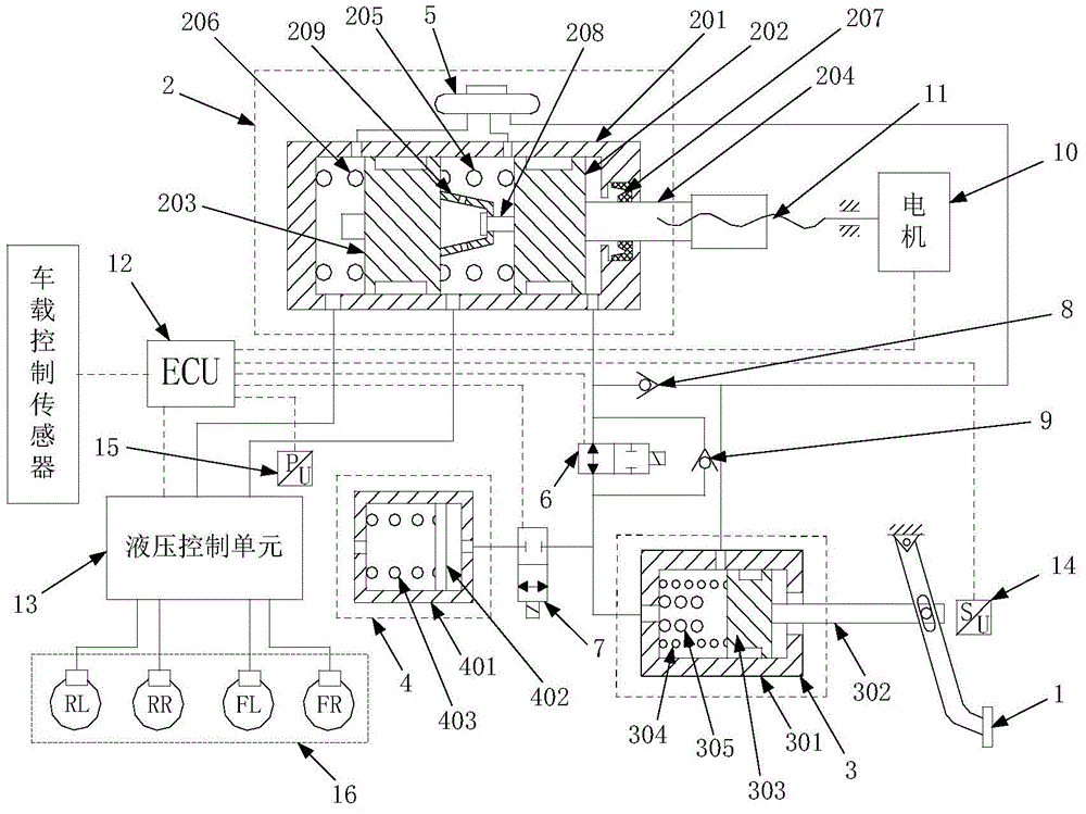
[0034] The electro-hydraulic composite brake system with the functions of electric brake booster and brake-by-wire includes a brake pedal 1, a master cylinder 2, a manpower cylinder 3, a pedal stroke simulator 4, a liquid storage tank 5, and 2 / 2 normally open Solenoid valve 6, 2 / 2 normally closed solenoid valve 7, first one-way valve 8, second one-way valve 9, motor 10, ball screw pair 11, electronic control unit (ECU) 12, hydraulic control unit 13, system Pedal displacement sensor 14, master cylinder pressure sensor 15 and four wheel cylinders 16, such as figure 1 shown.

[0035] The master cylinder 2 adopts a tandem three-chamber brake master cylinder, including a master cylinder body 201, a first piston 202, a second piston 203, a first piston push rod 204, a first piston return spring 205, a second Piston return spring 206. Wherein, the first piston 202 and the secon...


PUM


Abstract

The invention discloses an electro-hydraulic composite braking system with an electric braking assistant force and a brake-by-wire function. The electro-hydraulic composite braking system provided by the invention has various working modes In the case of an electric braking assistant force mode, a brake fluid is input into a master cylinder from a man-power cylinder by a brake pedal, and meanwhile, an electronic control unit controls the output torque of a motor to apply an assistant force, so as to output brake pressure to a wheel cylinder. In the case of a regenerative braking mode, the electronic control unit controls the on/off of an electromagnetic valve, the brake fluid is input into the simulation cavity of a pedal travel simulator from the man-power cylinder by the brake pedal so as to generate pressure and provide a brake pedal feeling; if automobile deceleration requirement can not be met by the regenerative braking, the electronic control unit controls the output torque of the motor so as to allow the master cylinder to output brake pressure into the wheel cylinder to assist friction brake. In case of an active braking mode, the electronic control unit controls the output torque of the motor so as to allow the master cylinder to output brake pressure to the wheel cylinder. The electro-hydraulic composite braking system provided by the invention has the advantages of integration of advantages of wire control and non-wire control working modes, small pressure fluctuation, and high pressure regulation precision.

Description

technical field [0001] The invention belongs to the technical field of automobile brake systems, and specifically relates to an electro-hydraulic composite brake system with functions of electric brake booster and wire-controlled brake. Background technique [0002] As the core safety component of automobiles, the braking system has undergone several major changes and improvements. From the initial leather friction brakes to drum and disc brakes, to vacuum boosters, electric boosters, anti-lock brake systems (ABS) and center valve brakes that are compatible with ABS but have a higher cost. moving master cylinder etc. In recent years, the research and development of brake-by-wire (Brake-by-wire), such as electro-hydraulic brake (EHB) and electro-mechanical brake (EMB), has sprung up. [0003] At present, most automobile hydraulic braking systems use vacuum power assist, and a few cars use other forms of power assist devices such as electric power assist (such as Nissan Moto...

Claims


Application Information

Patent Timeline
IPC IPC(8): B60T13/66B60T13/74B60T13/10
Inventor 邓伟文丁能根吴坚
Owner 南京经纬达汽车科技有限公司
Why Eureka
Try Eureka