
High-speed heat transfer oil roller

A technology of heat-conducting oil and rollers, which is applied in the field of ironing machines, can solve the problems of rotary joint bearing jamming, fire, and potential safety hazards, and achieve the effects of ensuring normal operation, high heat exchange efficiency, and removing potential safety hazards

Active Publication Date: 2016-02-24
无锡市艾可密封技术有限公司
View PDF5 Cites 1 Cited by
  • Summary
  • Abstract
  • Description
  • Claims
  • Application Information

AI Technical Summary

Problems solved by technology

[0006] Although the above two structures use heat conduction oil for circulation heating, the above two structures use a rotary joint directly installed on the roller shaft head for heating. The joints are prone to bearing jamming and cause fires, so there are potential safety hazards

Method used

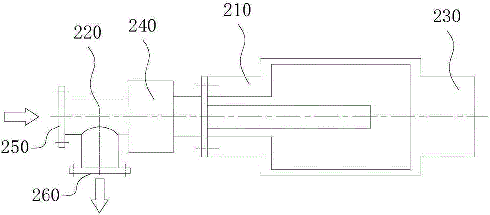

Image

  • High-speed heat transfer oil roller
  • High-speed heat transfer oil roller
  • High-speed heat transfer oil roller

Examples


Embodiment Construction

[0039] The technical solutions of the present invention will be further described below in conjunction with the accompanying drawings and through specific implementation methods.

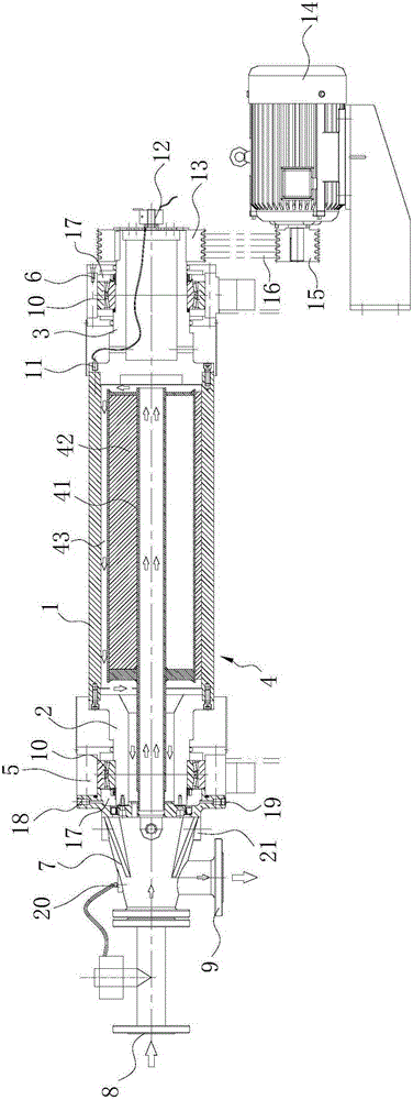
[0040] Such as image 3 In the shown embodiment, the new high-speed heat-conducting oil roller of the present invention includes a cylinder body 1, and the two ends of the cylinder body 1 are respectively provided with a first roller shaft head 2 and a second roller shaft head for connecting with a power source 3. The cylinder body 1 is provided with an oil circulation pipeline 4 for circulating heating on the outer surface of the cylinder body 1, the first bearing housing 5 is provided on the first roller shaft head 2, and the second roller shaft head 3 is provided The second bearing seat 6, between the first bearing seat 5 and the first roller shaft head 2 and between the second bearing seat 6 and the second roller shaft head 3 are all provided for rotating the cylinder body 1 around its axis. Be...


PUM


Abstract

The invention discloses a high-speed heat-transfer oil roller. The high-speed heat-transfer oil roller comprises a roller body, wherein a first roller spindle head and a second roller spindle head for connection with a power source are arranged at the two ends of the roller body, an oil line circulating pipeline for circularly heating the outer surface of the roller body is arranged in the roller body, a first bearing pedestal is arranged on the first roller spindle head, a second bearing pedestal is arranged on the second roller spindle head, bearings enabling the roller body to rotate around the axes of the bearings are arranged between the first bearing pedestal and the first roller spindle head and between the second bearing pedestal and the second roller spindle head, a rotary sealing device for oil inlet and oil outlet is detachably arranged at one side, which is far away from the roller boy, of the first bearing pedestal, and an oil inlet for connection with an inlet end of the oil line circulating pipeline and an oil outlet for connection with an outlet end of the oil line circulating pipeline are formed in the rotary sealing device. The high-speed heat-transfer oil roller disclosed by the invention is simple in structure and high in heat transfer efficiency; the blocking phenomenon and potential safety hazards are avoided in the using process of the high-speed heat-transfer oil roller.

Description

technical field [0001] The invention relates to the technical field of ironing machines, in particular to a high-speed heat-conducting oil roller. Background technique [0002] In the textile printing and dyeing industry, it is usually necessary to iron the fabric in the finishing process, so as to improve the surface gloss, handle and appearance of the fabric, and improve the quality of the fabric. The equipment generally used in the ironing process is an ironing machine. The main part of the ironing machine is the roller for ironing. The fabric is ironed and tapped by the heated roller, which can increase the luster and feel of the fabric and improve the texture of the fabric. quality. [0003] At present, the structure of the ironing machine roughly has the following two types: [0004] 1. Use electric heating to heat the roller surface of the ironing machine. For example, the Chinese patent document CN201770863U discloses a "ironing machine", which includes an ironing...

Claims


Application Information

Patent Timeline
Patent Type & Authority Patents(China)
IPC IPC(8): D06C15/08
Inventor 周存华戴永斌
Owner 无锡市艾可密封技术有限公司
Learn More