
Side wall concrete construction method employing side wall trolley

A construction method and technology of a wall trolley, which are applied in the fields of formwork/formwork/work frame, on-site preparation of building components, construction, etc., can solve the problem of slow formwork assembly speed, high labor intensity of workers, and lap jointing of steel pipe brackets. major problems, to achieve the effect of improving overall stability and construction quality, improving stability and construction speed, and improving stability and construction efficiency

Active Publication Date: 2015-05-20
GUANGZHOU XINQIAO CONSTR SERVICE +1
View PDF4 Cites 2 Cited by
  • Summary
  • Abstract
  • Description
  • Claims
  • Application Information

AI Technical Summary

Problems solved by technology

[0003] 1. The amount of lap joint of the steel pipe support is large, and the lap speed is slow;
[0004] 2. When installing wooden formwork, the operating space is narrow, the working environment is poor, and the formwork assembly speed is slow;
[0005] 3. It is difficult to guarantee the quality of the overlapping of formwork and steel pipe support, and the reliability is poor. When concrete is poured, it is easy to cause deformation of the side wall or concrete leakage;
[0006] 4. Wooden formwork has been assembled many times, and the concrete surface has poor flatness, and joints are prone to misalignment;
[0007] 5. It takes a long time to dismantle turnover materials such as wooden formwork and its brackets, the turnover speed is slow, and the usage is large;
[0008] 6. The technical requirements for workers are high, the labor intensity of workers is high, the number of workers required is large, the efficiency is low, and the labor cost is high

Method used


Image

  • Side wall concrete construction method employing side wall trolley
  • Side wall concrete construction method employing side wall trolley
  • Side wall concrete construction method employing side wall trolley

Examples


Embodiment Construction

[0043] The specific implementation manner of the present invention will be further described in detail below in conjunction with the accompanying drawings.

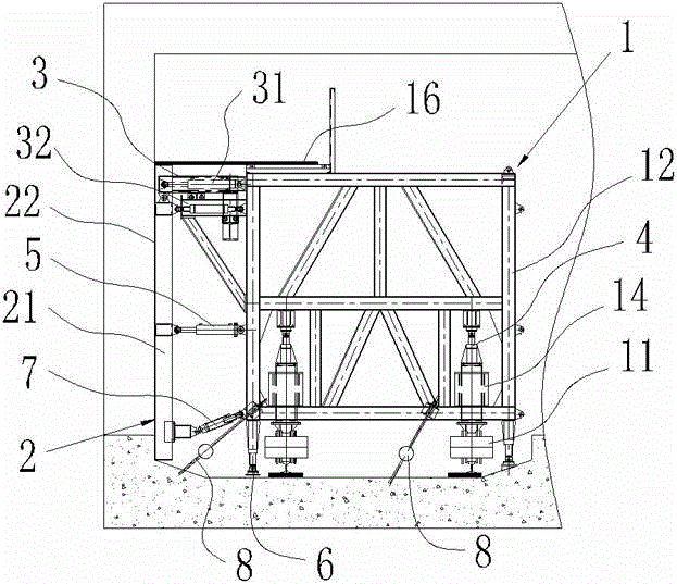
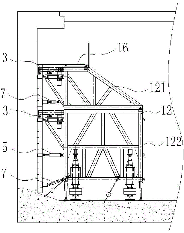
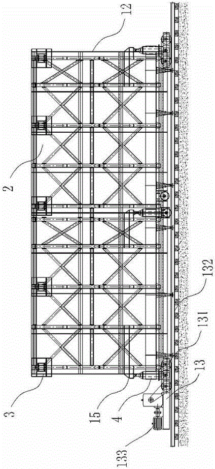
[0044] see also Figure 1~4 As shown, an embodiment of a side wall concrete construction method using a side wall trolley, wherein the applied side wall trolley is a side wall trolley unit or a longitudinal splicing of several side wall trolley units. The wall trolley unit includes a trolley moving and fixing system 1, and a steel formwork connection positioning system 2. In the embodiment, the designed length of the side wall trolley is 12m. In order to meet certain construction conditions, it can be split into two 6m side wall trolleys for use. The following are all described with the embodiment of the side wall trolley with a length of 12m after splicing.

[0045] The trolley moving and fixing system 1 includes a base 11 provided with a steel column 14 , a beam frame assembly 12 movably connected to the steel column ...


PUM


Abstract

The invention discloses a side wall concrete construction method employing a side wall trolley. The employed side wall trolley is formed by a side wall trolley unit or longitudinal splicing of a plurality of side wall trolley units, the side wall trolley unit comprises a trolley moving and fixing system and a steel moulding plate connecting and positioning system; the construction steps are the followings in sequence: paving a walking track, precoating a release agent, enabling the trolley to move and take place, adjusting a screw jack, repeatedly adjusting an extension-type cantilever beam and a hydraulic jack, adjusting a bearing jack, mounting a lateral screw rod jack, mounting a foot margin inhaul cable, mounting an anti-floating screw rod jack, mounting an opposite-support pipe fitting, mounting a closing-up net and a water stop steel plate, casting concrete, stripping and the like, that building a steel pipe support and a spliced template is not required can be achieved, after the adoption of the invention, the mounting and the demounting speeds are fast, three-direction accurate adjustment can be achieved, the construction is stable and reliable, the concrete surface flatness is good, and joint deviation is small.

Description

technical field [0001] The invention relates to a side wall concrete construction method, in particular to a side wall concrete construction method using a side wall trolley. Background technique [0002] At present, the concrete construction of the side wall generally adopts the construction method of full-wall bracket method + wooden formwork. This process needs to build a steel pipe support with the same width as the foundation pit in the foundation pit, and then assemble the wooden formwork piece by piece. Therefore, there are the following problems in actual construction: [0003] 1. The amount of lap joint of the steel pipe support is large, and the lap speed is slow; [0004] 2. When installing wooden formwork, the operating space is narrow, the working environment is poor, and the formwork assembly speed is slow; [0005] 3. It is difficult to guarantee the quality of the overlapping of formwork and steel pipe support, and the reliability is poor. When concrete is ...

Claims


Application Information

Patent Timeline
Patent Type & Authority Patents(China)
IPC IPC(8): E04G11/34
Inventor 丁昌银何炳泉陈慕贞莫劲蒋明曦黎玉奇唐伟才黄平宇黎文宪柯德辉雷雄武邱建涛黎文龙秦健新何登甲莫莉
Owner GUANGZHOU XINQIAO CONSTR SERVICE
Learn More