Hydraulic joint used for clamping test piece with superfine pipe diameter
A technology of hydraulic joints and test pieces, applied in the field of aerospace science, can solve the problems of increased production cost, low production efficiency, low positioning accuracy, etc., and achieve the effect of saving cost and improving production efficiency
- Summary
- Abstract
- Description
- Claims
- Application Information
AI Technical Summary
Problems solved by technology
Method used
Image

Examples
Embodiment Construction
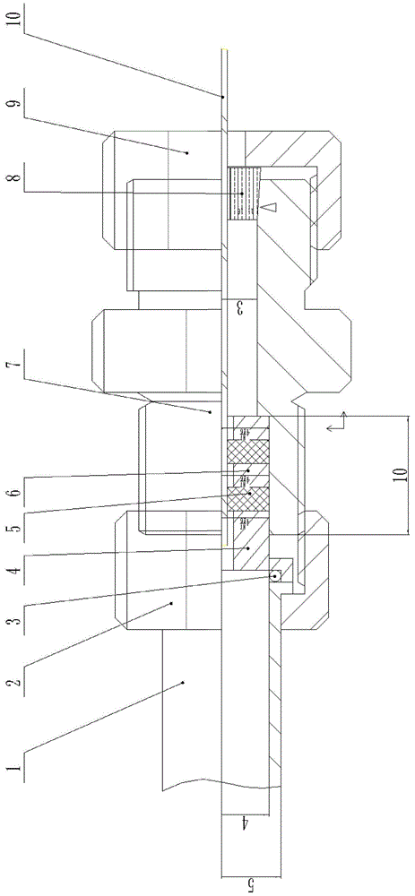
[0019] See figure 1 , the present invention is a hydraulic joint for clamping micro-diameter test pieces, which includes: an improved pipeline pressure inlet joint part, a sealed clamping part, and an improved pipeline pressure outlet joint part, and the positional connection relationship between them is : The improved pipeline pressure inlet joint part is located at the left end of the sealing clamping part, and the two are connected by threads; the improved pipeline pressure outlet joint part is located at the right end of the sealing clamping part, and the two are connected by threads.
[0020] The improved pipe pressure inlet joint part includes two parts: hydraulic pipe 1 and hydraulic pipe nut 2 at the left end, which are socketed; this part is located on the left side of the joint main body 7, and the hydraulic pipe nut 2 can be selected to cooperate with the standard part of the joint main body The nut of the standard part, which can rotate freely relative to the hydra...
PUM
 Abstract
Description
Claims
Application Information
PatSnap Eureka turns technology decisions into work you can execute. Powered by our Innovation Knowledge Graph, it runs expert workflows across engineering, life sciences, materials and intellectual property. Get your review-ready output in minutes.


