
Device for measuring light distribution in crop canopy

A measuring device and crop canopy technology, applied in the direction of measuring device, optical radiation measurement, electric device, etc., can solve the problem of not being able to measure photosynthetically active radiation information of multiple arbitrary designated points at the same time, expensive, difficult to install the designated position of plant leaves, etc. question

Active Publication Date: 2014-02-05
BEIJING RES CENT FOR INFORMATION TECH & AGRI
View PDF8 Cites 11 Cited by
  • Summary
  • Abstract
  • Description
  • Claims
  • Application Information

AI Technical Summary

Problems solved by technology

[0005] However, the main defects of the above-mentioned light distribution measuring device are: the disadvantages of the first type of line measuring device are that the measurement position is difficult to adjust, the measurement requires a lot of manual intervention, and it is easy to affect the shape of the crop canopy, the measured value stays at the statistical level, and the specified position cannot be measured photosynthetically active radiation information; the second type of point-type measuring instrument is thick and expensive, and it is difficult to install it on the designated position of the plant leaf. Even if it is installed on the leaf, the position of the point-type light distribution measuring device is easily affected by the shape of the leaf. In addition, none of the above light distribution measuring devices can simultaneously measure the photosynthetically active radiation information of multiple arbitrary designated points
[0006] The patent application number 201210125131.3 provides a light distribution measurement device and method in the crop canopy. The light distribution measurement device in the crop canopy can continuously measure the photosynthetically active radiation information of multiple designated points, but the position information of these designated points is not Clear, not conducive to people's understanding of the light distribution of crop canopies

Method used


Image

  • Device for measuring light distribution in crop canopy

Examples


Embodiment Construction

[0022] The specific implementation manners of the present invention will be further described in detail below in conjunction with the accompanying drawings and embodiments. The following examples are used to illustrate the present invention, but are not intended to limit the scope of the present invention.

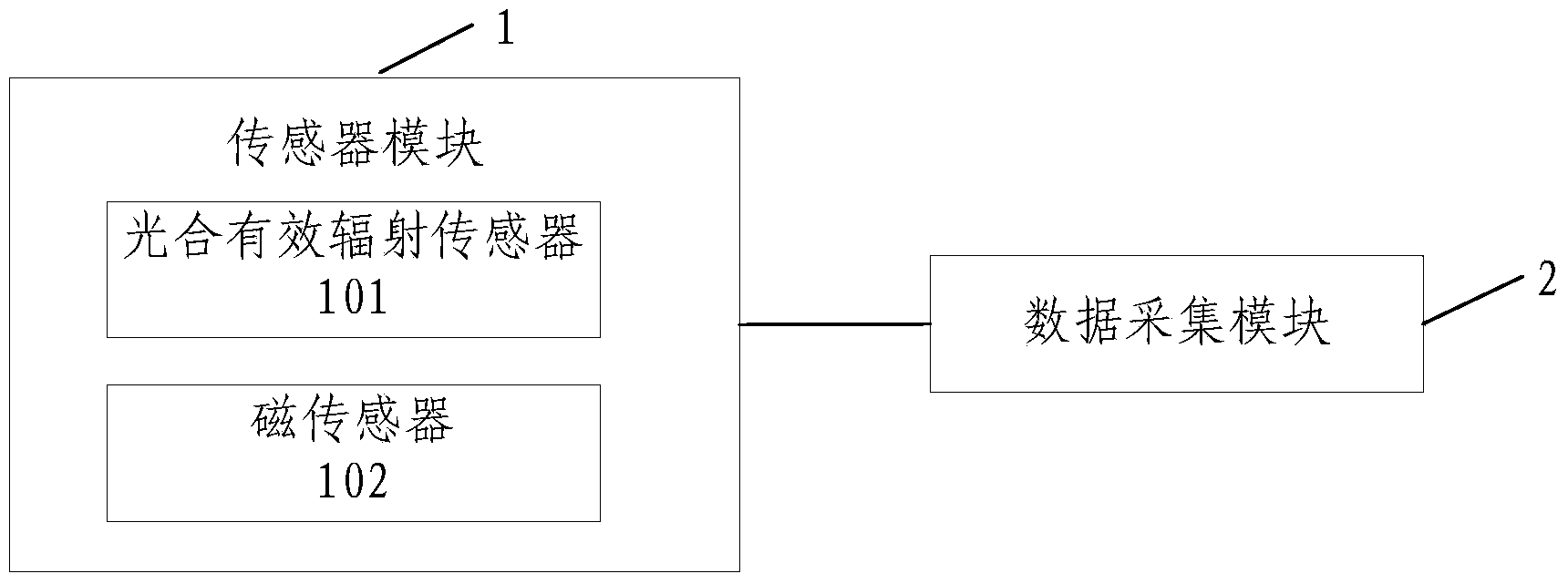
[0023] figure 1 It is a structural diagram of a light distribution measuring device in a crop canopy provided by an embodiment of the present invention, including a sensor module 1 and a data acquisition module 2;

[0024] The sensor module includes a photosynthetically active radiation sensor 101 and a magnetic sensor 102, the photosynthetically active radiation sensor 101 is used to measure the photosynthetically active radiation information of the points to be measured in the plant canopy, and the magnetic sensor 102 is used to measure the photosynthetically active radiation information of the points to be measured point location information;

[0025] Wherein, the mag...


PUM


Abstract

The invention provides a device for measuring light distribution in a crop canopy. The device comprises a sensor module and a data acquisition module. The sensor module comprises a photosynthetic active radiation sensor and a magnetic sensor, the photosynthetic active radiation sensor is used for measuring photosynthetic active radiation information of a point to be measured in the plant canopy, and the magnetic sensor is used for measuring position information of the point to be measured. The module acquisition module connected with the sensor module and is used for acquiring the photosynthetic active radiation information and the position information measured by the sensor module and storing the acquired photosynthetic active radiation information and position information. The device for measuring light distribution in the crop canopy can conduct synchronous measurement on the photosynthetic active radiation information and the position information of the point to be measured in the crop canopy and provide an effective method which enables people to have a more accurate understanding of light distribution in the crop canopy.

Description

technical field [0001] The invention relates to the technical field of light distribution measurement, in particular to a light distribution measurement device in a crop canopy. Background technique [0002] The measurement of radiation distribution in plant canopy lays the foundation for the study of radiation transfer and distribution in canopy, and is the main method to verify the radiation model. [0003] In recent years, with the development of modern automatic detection technology, a variety of specialized instruments for observing light in the canopy of crops have emerged. Such as: LI-190SA point-type and LI-191SA line-type photosynthetically active radiation light quantum measuring instrument produced by LI-COR; SunScan canopy analyzer produced by Delta-T Instrument Company of the United Kingdom; AccuPAR canopy analysis of Decagon Instrument Company of the United States The main body of the instrument is 80 PAR probes evenly distributed on an 80cm probe rod, and thr...

Claims


Application Information

Patent Timeline
Patent Type & Authority Applications(China)
IPC IPC(8): G01J1/00G01B7/00
Inventor 郭新宇温维亮肖伯祥王传宇陆声链
Owner BEIJING RES CENT FOR INFORMATION TECH & AGRI
Learn More