Endurance testing device of automobile sliding door traveling wheel arms and locking combining pieces

A technology of durability test and wheel arm, which is applied in the testing of mechanical components, testing of machine/structural components, measuring devices, etc. It can solve the problems of high cost, many influencing factors, and lack of pertinence, so as to speed up technology development Cycle time, saving development costs, and highly targeted effects

Inactive Publication Date: 2014-02-05
SAIC-GM-WULING AUTOMOBILE CO LTD
View PDF6 Cites 4 Cited by
  • Summary
  • Abstract
  • Description
  • Claims
  • Application Information

AI Technical Summary

Problems solved by technology

At present, many tests verify the performance of the stopper and the wheel arm through the switch test of the entire door system. This method has many influencing factors, is not pertinent, and the test is complicated, high in cost, and low in efficiency. Therefore, it is necessary to A test method specially aimed at the stop assembly and the wheel arm system to meet the needs; in the actual work of the stop assembly and the wheel arm, there will be complex working conditions such as different frequencies, different temperatures, humidity, vibrations, etc. Therefore, there is a need for a method and device capable of performing endurance tests on the running wheel arm and the stop assembly under various conditions such as different frequencies, different humidity, high and low temperature, and vibration.

Method used


Image

  • Endurance testing device of automobile sliding door traveling wheel arms and locking combining pieces

Examples


Embodiment Construction

[0022] The present invention will be described in further detail below in conjunction with the accompanying drawings.

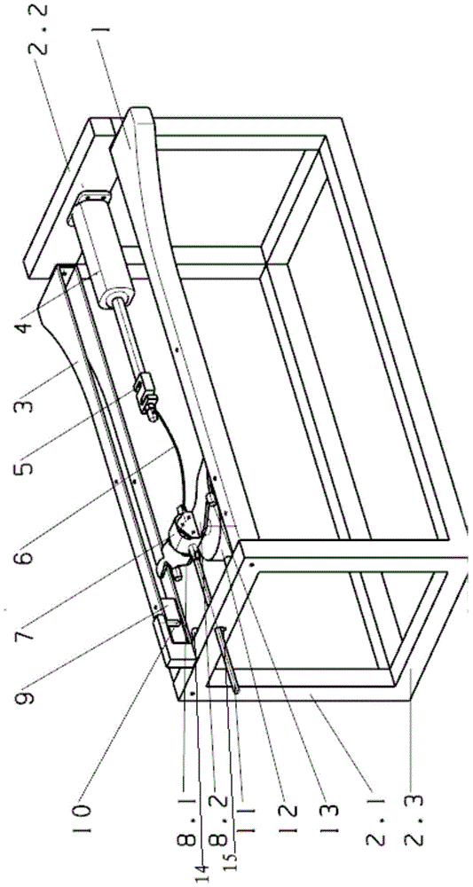
[0023] Such as figure 1 The shown durability test device for a wheel arm and a stop assembly of an automobile sliding door of the present invention includes a stand 2, and the stand includes a front frame 2.1, a rear frame 2.2, and a bottom frame 2.3 vertically arranged and parallel to each other. The two ends of the guide rail 1 are respectively fixedly connected to the bottom of the front frame 2.1 and the rear frame 2.2; the two ends of the left guide rail 3 are respectively fixedly connected to the top of the left end side of the front frame 2.1 and the rear frame 2.2; the two ends of the right guide rail 1 are respectively fixedly connected to the front frame 2.1 and the top of the right end side of the rear frame 2.2; the left guide rail 3 and the right guide rail 1 are horizontally symmetrically arranged and parallel to each other. A guide hole 15 per...


PUM


Abstract

The invention provides an endurance testing device of automobile sliding door traveling wheel arms and locking combining pieces. The endurance testing device of the automobile sliding door traveling wheel arms and the locking combining pieces comprises a left guiding rail and a right guiding rail, wherein the left guiding rail and the right guiding rail are horizontally and symmetrically fixed to a table frame and are mutually parallel to each other. The left traveling wheel arm and the right traveling wheel arm are symmetrically arranged at the two ends of a connecting rod and are connected with the left guiding rail and the right guiding rail respectively in a sliding mode; one end of an actuator is fixedly connected with the center of the table frame, the other end of the actuator is connected with a force sensor, a connecting rope and a guiding rod in sequence, the actuator is coaxially arranged with the connecting rod, and a heavy article is hung below the connecting rod; the left guiding rail and the right guiding rail are respectively provided with one locking combining piece and the left traveling wheel arm and the right traveling wheel arm are respectively provided with locking rubber matched with a locking block; a photosensitive sensor senses whether the locking rubber reaches the position where the locking rubber is in contact with each locking block or not. The endurance test device of the automobile sliding door traveling wheel arms and the locking combining pieces is simple in structure, can simulate the actual motion condition when a sliding door is in actual operation, avoids the situation that the whole sliding door serves as a tested object, and the durability and the reliability of the locking combining pieces and the traveling wheel arms can be rapidly verified.

Description

technical field [0001] The invention relates to the test field of automobile production, in particular to an endurance test device for a running wheel arm and a stop joint of an automobile sliding door. Background technique [0002] The limiting function of the stop assembly and the sliding and supporting functions of the wheel arm are two important functional indicators of the sliding door of the car, and are also the key technology of the sliding door. The quality and performance of the stop assembly and the running wheel arm are important indicators of whether a car is qualified, so the test verification of the stop assembly and the running wheel arm is necessary. At present, many tests verify the performance of the stopper and the wheel arm through the switch test of the entire door system. This method has many influencing factors, is not pertinent, and the test is complicated, high in cost, and low in efficiency. Therefore, it is necessary to A test method specially ai...

Claims


Application Information

Patent Timeline
Patent Type & Authority Applications(China)
IPC IPC(8): G01M13/00
Inventor 赖玉龙卢厚柱尹恒苏定芳
Owner SAIC-GM-WULING AUTOMOBILE CO LTD
Why Eureka
Try Eureka