

display device
A display device and display surface technology, applied in the direction of identification devices, instruments, etc., to achieve the effect of zero dead angle of sight, improve space utilization, and reduce thickness
- Summary
- Abstract
- Description
- Claims
- Application Information
AI Technical Summary
Problems solved by technology
Method used
Image

Examples
no. 1 approach
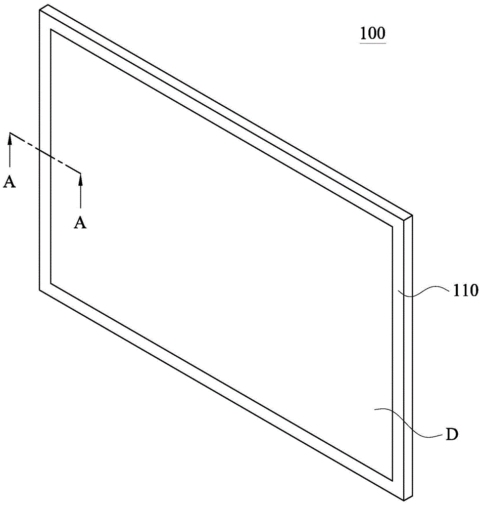
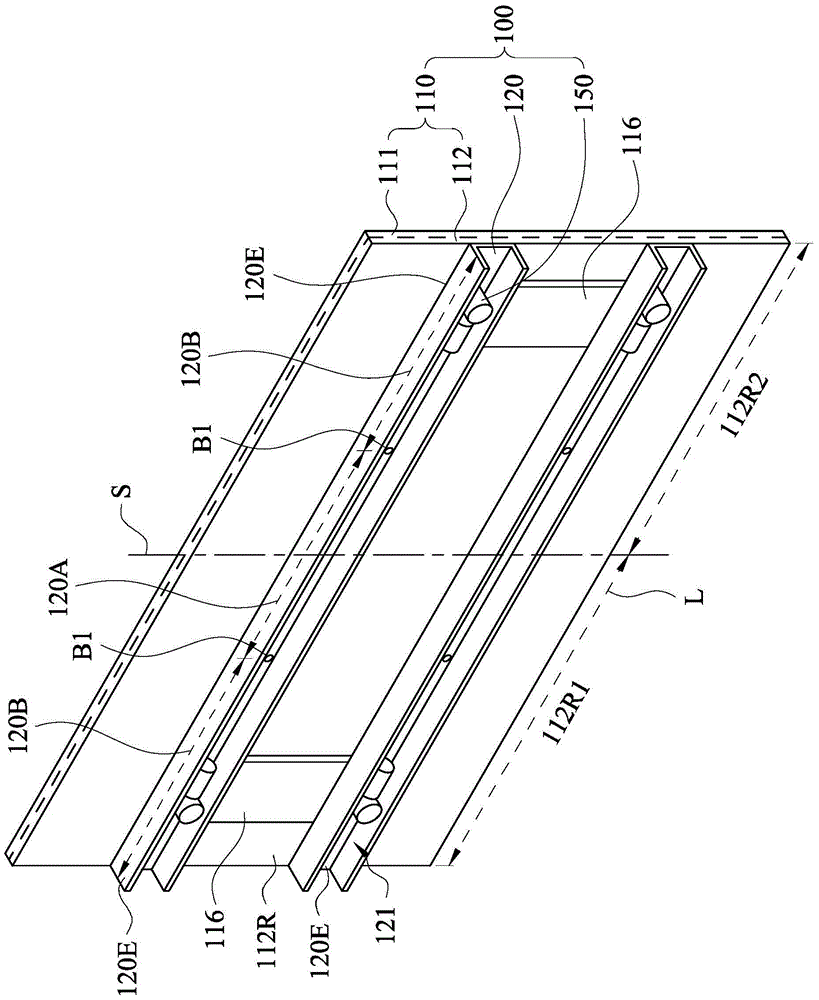
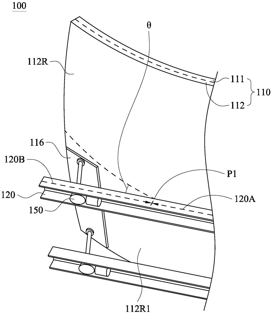
[0038] figure 1 A front perspective view of the display device 100 according to the first embodiment is shown. figure 2 draw figure 1 The rear perspective view of the display device 100 of FIG. Such as figure 2 As shown, a display device 100 includes a panel module 110 , a supporting frame 120 and a pushing unit 150 . The panel module 110 is bendable, and the panel module 110 includes a display panel 111 and a backplane 112 . The backplane 112 is stacked with the display panel 111 . The display panel 111 has a display surface D ( figure 1 ). The carrying frame 120 is fixed on the side of the back plate 112 opposite to the display panel 111 (hereinafter referred to as the back side 112R). The pushing unit 150 is telescopically connected to the rear surface 112R of the backboard 112 .
[0039] Figure 3A draw figure 2 Partial rear perspective view of the pushing unit 150 pushing the backboard 112 . Figure 3B draw figure 1 A partial front perspective view when the...
no. 2 approach
[0056] Figure 5 A rear view of the display device 101 according to the second embodiment is shown. Such as Figure 5 As shown, the display device 101 of the second embodiment and figure 2 The display device 100 is the same as above, except that the back plate 112 of the second embodiment is further fixed with a rigid plate body 114, the rigid plate body 114 is located between the display panel 111 and the supporting frame 120, and the area of the rigid plate body 114 is smaller than that of the back plate 112 and its position approximately overlaps with the imaginary midline S. In this way, the rigid plate body 114 can further enhance the overall structural strength of the panel module 110 .
[0057] Figure 5 The carrying frame 120 is not limited to be fixed on the backboard 112 or the rigid board body 114 . When the carrier frame 120 is fixedly connected to the rigid board body 114 , the panel module 110 can be more firmly combined with the carrier frame 120 , preve...
no. 3 approach
[0063] Figure 7 A rear view of the display device 102 according to the third embodiment is shown. Figure 8 draw Figure 7 A partial perspective view of the pushing unit 150 pushing the backboard 112 . Such as Figure 7 , the display device 102 of the third embodiment and Figure 5 The display device 101 is similar to the display device 101 of the third embodiment, except that the display device 102 of the third embodiment further includes at least one connecting rib 122 connecting the two supporting frames 120 across. Therefore, compared to Figure 5 The support strength provided by the carrier frame 120 to the panel module 110, Figure 7 The connecting ribs 122 can further reinforce the required supporting strength of the panel module 110 .
[0064] For example, if Figure 7 shown, but the present invention is not limited Figure 7 The two connecting ribs 122 are respectively located in the first area 112R1 and the second area 112R2, both connecting the two supporti...
PUM
 Abstract
Description
Claims
Application Information