A Monocular Ranging Method Based on Plane Mirror

A monocular ranging and plane mirror technology, applied in the field of ranging, which can solve problems such as application limitations

Active Publication Date: 2021-09-10
LOW SPEED AERODYNAMIC INST OF CHINESE AERODYNAMIC RES & DEV CENT
View PDF46 Cites 0 Cited by
  • Summary
  • Abstract
  • Description
  • Claims
  • Application Information

AI Technical Summary

Problems solved by technology

However, a flat ground is a relatively ideal assumption. The application of this method is limited in the case of undulating road surfaces, external targets that are far away from the road surface without direct contact, and road surfaces missing.

Method used


Image

  • A Monocular Ranging Method Based on Plane Mirror
  • A Monocular Ranging Method Based on Plane Mirror

Examples


Embodiment Construction

[0030] The following description provides many different embodiments, or examples, for implementing various features of the invention. The elements and arrangements described in the following specific examples are only used to express the present invention in a concise manner, and are only used as examples rather than limiting the present invention.

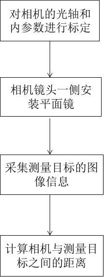
[0031] Embodiments of the present invention provide a monocular ranging method based on a plane mirror, such as figure 1 As shown, the steps include:

[0032] Step S1: Calibrate the main optical axis and internal parameters of the camera 10;

[0033] Step S2: install a plane mirror 20 on one side of the camera lens;

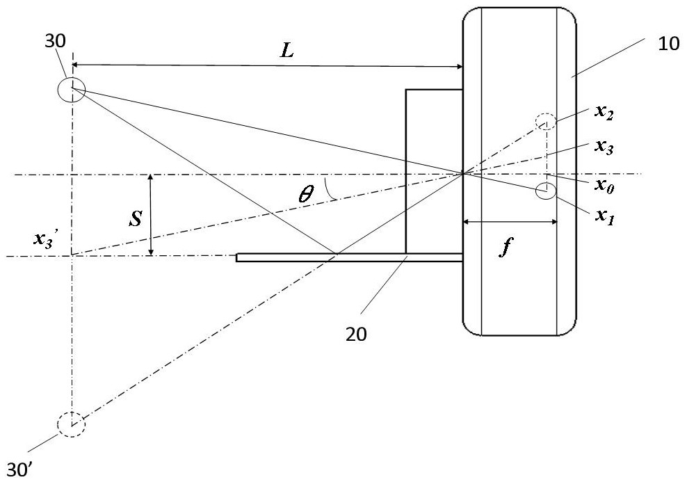
[0034] Step S3: Utilize the camera installed with the plane mirror to collect the image information of the real object of the measurement target 30 and the image information of the virtual image 30' of the measurement target in the plane mirror;

[0035] Step S4: Calculate the distance between the camera 10 and ...


PUM


Abstract

The present invention provides a monocular ranging method based on a plane mirror. The steps of the embodiment of the present invention include: Step S1: Calibrate the main optical axis and internal parameters of the camera; Step S2: Install a plane mirror on one side of the camera lens; Step S3 : using a camera installed with a plane mirror to collect the image information of the real object of measurement and the image information of the virtual image of the measurement target in the plane mirror; step S4: calculating the distance between the camera and the measurement target. The ranging method adopted in the present invention has the advantages of simple operation, simple and easy-to-understand calculation process, and high accuracy of ranging results.

Description

technical field [0001] The invention relates to the technical field of distance measurement, in particular to a monocular distance measurement method based on a plane mirror. Background technique [0002] In the prior art, there are binocular distance measurement and monocular distance measurement, among which monocular distance measurement has the characteristics of simple structure and convenient operation and is widely used. At present, there are three methods of monocular distance measurement: macular distance measurement, split image distance measurement, and peak (focal spot) distance measurement. Among the above three methods, the optical path difference is used in the macular distance measurement, which is limited by the structural scale of the monocular camera; the split-image distance measurement and peak (focal spot) distance measurement are both limited by the focal length of the camera lens and the pixel resolution . Due to these limitations, the range of mono...

Claims


Application Information

Patent Timeline
Patent Type & Authority Patents(China)
IPC IPC(8): G01C3/00G01B11/02G01B11/14G06T7/60
CPCG01B11/026G01B11/14G01C3/00G06T7/60
Inventor 胡站伟赵献礼左承林熊浩
Owner LOW SPEED AERODYNAMIC INST OF CHINESE AERODYNAMIC RES & DEV CENT
Why Eureka
Try Eureka