
Method for measuring phase difference of common-frequency signal with fixed phase drift

A technology with the same frequency signal and fixed phase shift, which is applied in the field of signal processing to achieve a wide range of applications

Inactive Publication Date: 2012-07-25
INST OF SEMICONDUCTORS - CHINESE ACAD OF SCI
View PDF0 Cites 0 Cited by
  • Summary
  • Abstract
  • Description
  • Claims
  • Application Information

AI Technical Summary

Problems solved by technology

[0007] The purpose of this invention is to provide a method for measuring the phase difference of the same-frequency signal by using a fixed phase shift. Based on the method of phase difference, a new way to deal with the problem of measuring phase difference in the time domain is proposed

Method used


Image

  • Method for measuring phase difference of common-frequency signal with fixed phase drift
  • Method for measuring phase difference of common-frequency signal with fixed phase drift
  • Method for measuring phase difference of common-frequency signal with fixed phase drift

Examples


Embodiment Construction

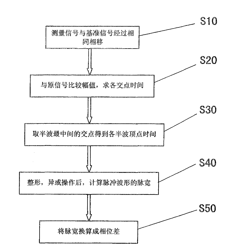
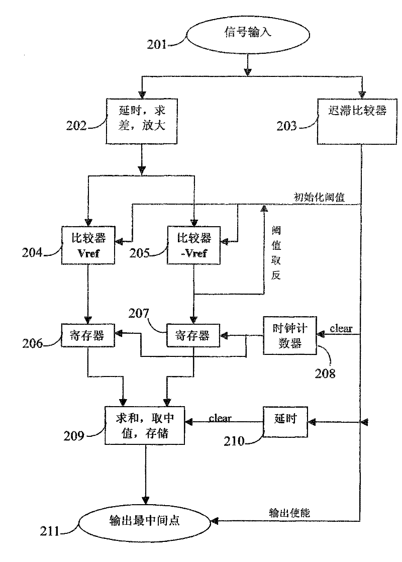
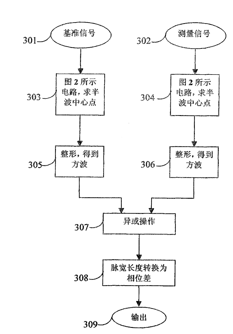
[0028] see figure 1 , figure 2 with image 3 Shown, a kind of method that utilizes fixed phase shift of the present invention to measure the phase difference of same-frequency signal, comprises:

[0029] Step 1 (S10): Two original signals with the same frequency containing only homogeneous harmonic components, ie, the reference signal and the measurement signal, undergo the same phase shift respectively to obtain two delayed signals. Such as image 3 As shown, the reference signal 301 and the measurement signal 302, as two objects of phase difference measurement, pass through two channels at first figure 2 The delay unit in module 202 shown in the figure obtains the delayed signal of the original signal. The present invention approximates the pole of the original signal through the intersection of the original signal and the delayed signal, so the delay time is not easy to be too long. The appropriate delay time should be selected. If the delay time is too short, it wil...


PUM


Abstract

The invention provides a method for measuring the phase difference of a common-frequency signal with fixed phase drift, which comprises the following steps of: respectively performing the same phase drift to two common-frequency original signals which only contain homogeneous harmonic component to obtain two time-delayed signals, wherein the common-frequency original signals are respectively to be a reference signal and a measurement signal; comparing the amplitude value of the two time-delayed signals after the same phase drift with the reference signal and the measurement signal, leading a pair of a positive threshold value and a negative threshold value at the front and the back of each intersection point to obtain two time points, and obtaining an intersection point time by taking thecenter of the two time points; repeating the step 2, obtaining one or a series of the time intersection point(s) within half-wave periods, and taking the middlemost intersection point time to be approximate to the peak time of the original signals in the half-wave periods; shaping the reference signal and the measurement signal to be two rectangular wave signals according to the peak time obtained in each half-wave period, and diversifying or operating the obtained two rectangular wave signals to obtain a pulse signal, wherein the width of the pulse signal is the time difference from the peakof the reference signal and the peak of the measurement signal; and converting the time difference to obtain the difference value of the phase position to be measured.

Description

technical field [0001] The invention belongs to the technical field of signal processing, in particular to a method for measuring the phase difference of signals of the same frequency by using a fixed phase shift. Background technique [0002] Phase difference measurement of periodic signals with the same frequency is widely used in signal analysis, circuit parameter testing, electrical technology, industrial automation, intelligent control, communication and electronic technology, etc. Determination of power factor angle, etc. [0003] There are many methods of phase difference measurement: traditional methods relying on analog devices, such as vector method, diode phase detection method, pulse counting method, etc., the measurement system is complex, special devices are required, and the hardware cost is high; in recent years, computers and digital signal processing The technology has made great progress, and the phase difference measurement is gradually developing toward...

Claims


Application Information

Patent Timeline
Patent Type & Authority Patents(China)
IPC IPC(8): G01R25/00
Inventor 鲁华祥龚国良边昳
Owner INST OF SEMICONDUCTORS - CHINESE ACAD OF SCI
Learn More