Grid drive circuit and array substrate and display panel thereof

A gate drive circuit and gate drive technology, used in static indicators, instruments, etc., can solve problems such as abnormal operation and screen display errors, and achieve the effects of extending service life, reducing the possibility of leakage and shortening working time.

Inactive Publication Date: 2014-02-05
SHENZHEN CHINA STAR OPTOELECTRONICS TECH CO LTD
View PDF5 Cites 34 Cited by
  • Summary
  • Abstract
  • Description
  • Claims
  • Application Information

AI Technical Summary

Problems solved by technology

However, the researchers of the present invention have found through long-term research and testing that the alternate operation of the second pull-down unit 50 and the third pull-down unit 60 is not very ideal. After the test, the second pull-down unit 50 and the third pull-down unit 60 in the gate drive unit tend to work abnormally, resulting in screen display errors

Method used


Image

  • Grid drive circuit and array substrate and display panel thereof
  • Grid drive circuit and array substrate and display panel thereof
  • Grid drive circuit and array substrate and display panel thereof

Examples


Embodiment Construction

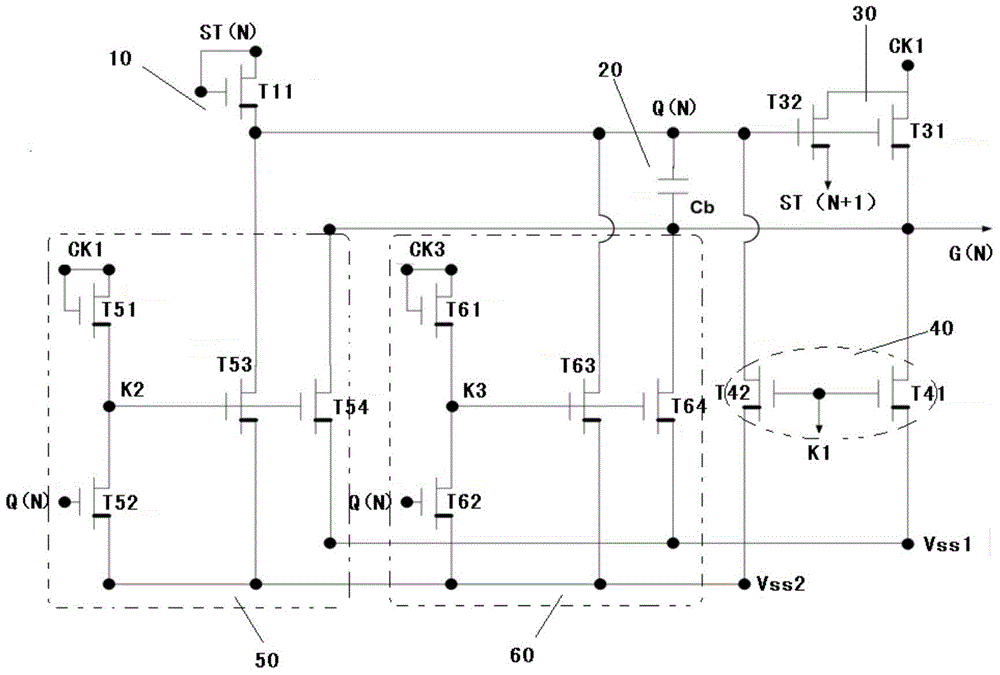
[0044] In order to illustrate the purpose, technical scheme and technical effect of the present invention, as follows figure 2 Taking the gate drive unit in a gate drive circuit as an example, the reasons for the above faults and the improvements made by the present invention are analyzed in detail. It should be noted that although the present invention is described with reference to this embodiment, it should not be limited thereto. Different types of display panels have different circuit structures, so any person skilled in the technical field of the present invention can modify the form and details of the implementation without departing from the spirit and scope of the present invention. make any modifications and changes.

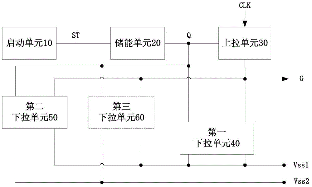
[0045] Such as figure 2 Shown is a schematic diagram of the circuit structure of an Nth-level gate drive unit in an existing gate drive circuit. As described in the background, the gate driving unit can be divided into a start-up unit 10 , an ener...


PUM


Abstract

The invention relates to a grid drive circuit and an array substrate and a display panel of the grid drive circuit. The grid drive circuit comprises multi-stage grid drive units, each stage of grid drive unit comprises a starting unit, an energy storage unit, a pulling-up unit, a first pulling-down unit and a second pulling-down unit, wherein the second pulling-down unit is coupled with the energy storage unit and a grid line and used for generating second control signals intermittently according to a driving voltage, a time pulse signal and a second reference voltage so that the driving voltage and a grid signal on the grid line can be pulled down to the second reference voltage. Besides, in order to prevent the problem because a leakage current exists between a first reference voltage and the second reference voltage, a chip responsible for providing the reference voltages is burnt, transistors which are located between the first reference voltage and the second reference voltage and the leakage current may flow through are further changed to a plurality of transistors in series connection so that the electric leakage probability is reduced. The grid drive circuit and the array substrate of the grid drive circuit are enhanced in reliability, the service life is long, and the grid drive circuit can be applied to various display panels.

Description

technical field [0001] The present invention relates to image display driving technology, in particular to a gate driving circuit, an array substrate and a display panel thereof. Background technique [0002] The existing liquid crystal display device includes a plurality of pixel units, and a gate driving circuit and a source driving circuit for driving the pixel units to work. Wherein, the gate driving circuit includes multi-level gate driving units, and these gate driving units sequentially output gate signals through the gate lines coupled to them, and control the corresponding switch transistors in the display area to turn on, so that the source driving circuit The output data signal is written into the corresponding pixel unit for image display. Therefore, the reliability of the gate drive circuit has a decisive impact on correct imaging. Such as figure 1 As shown, at present, the structure of the gate drive unit of the gate drive circuit used by mainstream display ...

Claims


Application Information

Patent Timeline
Patent Type & Authority Applications(China)
IPC IPC(8): G09G3/36
CPCG09G3/3677
Inventor 郭平昇
Owner SHENZHEN CHINA STAR OPTOELECTRONICS TECH CO LTD
Why Eureka
Try Eureka