Grid drive circuit and array substrate and display panel thereof

A gate drive circuit and gate drive technology, used in static indicators, static memories, instruments, etc., can solve the problems of transistor threshold voltage shift, failure to turn on normally, gate drive circuit failure to work normally, etc. Enhanced reliability, improved effects of adverse effects

Inactive Publication Date: 2014-02-05
TCL CHINA STAR OPTOELECTRONICS TECH CO LTD
View PDF6 Cites 29 Cited by
  • Summary
  • Abstract
  • Description
  • Claims
  • Application Information

AI Technical Summary

Problems solved by technology

[0003] In view of the above problems, the present invention provides a gate drive circuit and its array substrate and display panel, which can effectively solve the problem that the transistor in the prior art cannot be turned on normally due to threshold voltage shift, which leads to the failure of the gate drive circuit. problem with normal work

Method used


Image

  • Grid drive circuit and array substrate and display panel thereof
  • Grid drive circuit and array substrate and display panel thereof
  • Grid drive circuit and array substrate and display panel thereof

Examples


Embodiment Construction

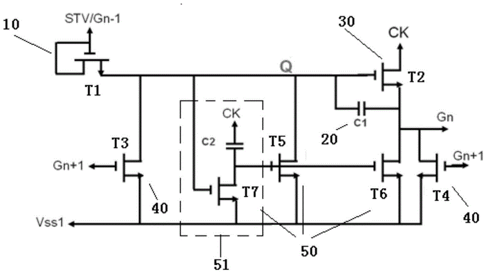
[0045] In order to illustrate the purpose, technical solution and technical effect of the present invention, a 7T2C gate drive unit (consisting of seven transistors and two capacitors) is taken as an example to describe in detail the gate drive circuit when the gate drive circuit works with reference to the accompanying drawings. The phenomenon of threshold voltage shift occurs in the transistor of the driving unit, and the improvement made by the present invention to solve this problem. It should be noted that although the present invention is described with respect to the 7T2C gate drive unit and its thin film transistor, it should not be limited thereto. Gate drive units, gate drive circuits and their array substrates and display panels designed by different manufacturers have different circuit structures, and the transistors used may not be thin-film transistors. Therefore, anyone skilled in the technical field of the present invention , without departing from the spirit d...


PUM


Abstract

The invention relates to a grid drive circuit and an array substrate and a display panel of the grid drive circuit. The grid drive circuit comprises multi-stage grid drive units, and each stage of grid drive unit comprises a starting unit for transmitting a starting signal, an energy storage unit for executing charging according to the starting signal in order to output a driving voltage, an pulling-up unit, a first pulling-down unit, a second pulling-down unit and a third pulling-down unit, wherein the pulling-up unit, the first pulling-down unit, the second pulling-down unit and the third pulling-down unit work under the action of the driving voltage. The third pulling-down unit is used for pulling the driving voltage to a second reference voltage in a perpendicular flyback period so that an opposite bias voltage can be applied to grids and sources and/or grids and drains of transistors in the grid drive circuit, threshold voltages of the transistors in forward migration can have reverse migration, bad influences on the grid drive circuit caused by threshold voltage migration of the transistors can be effectively eliminated, and the grid drive circuit and the array substrate and the display panel of the grid drive circuit can work more reliably.

Description

technical field [0001] The present invention relates to liquid crystal display drive technology, in particular to a gate drive circuit, an array substrate and a display panel thereof. Background technique [0002] The existing liquid crystal display panel includes a plurality of pixel units, and a gate driving circuit and a source driving circuit for driving the pixel units to work. Wherein, the gate driving circuit includes multi-level gate driving units, and these gate driving units sequentially output gate signals through the gate lines coupled to them, and control the corresponding switch transistors in the display area to turn on, so that the source driving circuit The output data signal is written into the corresponding pixel unit for image display. Therefore, the reliability of the operation of the gate drive unit has a decisive influence on the correct imaging. At present, the structure of the gate drive unit of the gate drive circuit used by mainstream liquid crys...

Claims


Application Information

Patent Timeline
Patent Type & Authority Applications(China)
IPC IPC(8): G09G3/36G11C19/28
CPCG09G3/3677G11C19/28
Inventor 郭平昇
Owner TCL CHINA STAR OPTOELECTRONICS TECH CO LTD
Why Eureka
Try Eureka