Eureka AIR delivers breakthrough ideas for toughest innovation challenges, trusted by R&D personnel around the world.

Magnetic ring stator cylindrical linear switch reluctance motor

A technology of switched reluctance motor and ring stator, which is applied in the direction of magnetic circuit shape/style/structure, electromechanical devices, electrical components, etc., and can solve the problem of low power density and propulsion density, low motor propulsion density, and motor mover weight Major and other issues

Active Publication Date: 2014-02-05
SHANDONG UNIV
View PDF6 Cites 2 Cited by
  • Summary
  • Abstract
  • Description
  • Claims
  • Application Information

AI Technical Summary

Problems solved by technology

However, due to the characteristics of the reluctance torque, the propulsive force density of the motor is low. Therefore, it is an urgent problem to be solved to improve the propulsive force density of the cylindrical linear motor.
In addition, the existing cylindrical linear switched reluctance motor has a mover yoke, the motor mover is heavy, only a part of the magnetic circuit is effectively used when the winding is energized, the utilization rate of the ferromagnetic material of the motor is low, and the power density and propulsion density are low

Method used


Image

  • Magnetic ring stator cylindrical linear switch reluctance motor
  • Magnetic ring stator cylindrical linear switch reluctance motor
  • Magnetic ring stator cylindrical linear switch reluctance motor

Examples


Embodiment 1

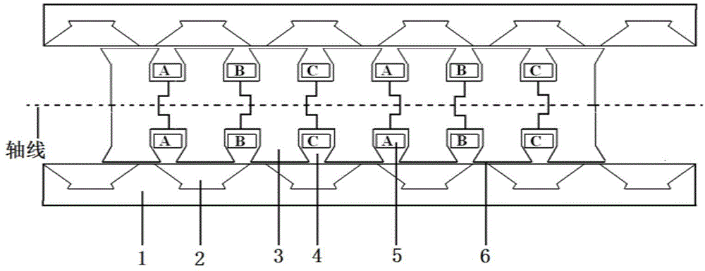
[0046] Such as figure 1As shown, the number of motor phases in this embodiment is m=3, the number of mover poles Pt=6, the number of stator poles Ps=4, the number of teeth contained in the mover cylinder Nt=7, and the number of annular mover slots contained in the mover cylinder is Qs=6, the number of stator magnetic conducting rings contained in the stator barrel is Ns≥5. This embodiment includes a non-magnetic stator sleeve 1, a stator magnetic ring 2 is placed inside the non-magnetic stator sleeve 1, and the stator magnetic ring 2 is uniformly fixed inside the non-magnetic stator sleeve 1 along the axial direction. The axial section of the magnetic ring 2 is trapezoidal, and the bottom is processed into a special shape so as to be fixed with the non-magnetic stator sleeve 1. A mover core 3 is arranged inside the non-magnetic stator sleeve 1, and the mover core 3 and the non-magnetic The magnetically permeable stator sleeve 1 is coaxially installed, and the mover core 3 is ...

Embodiment 2

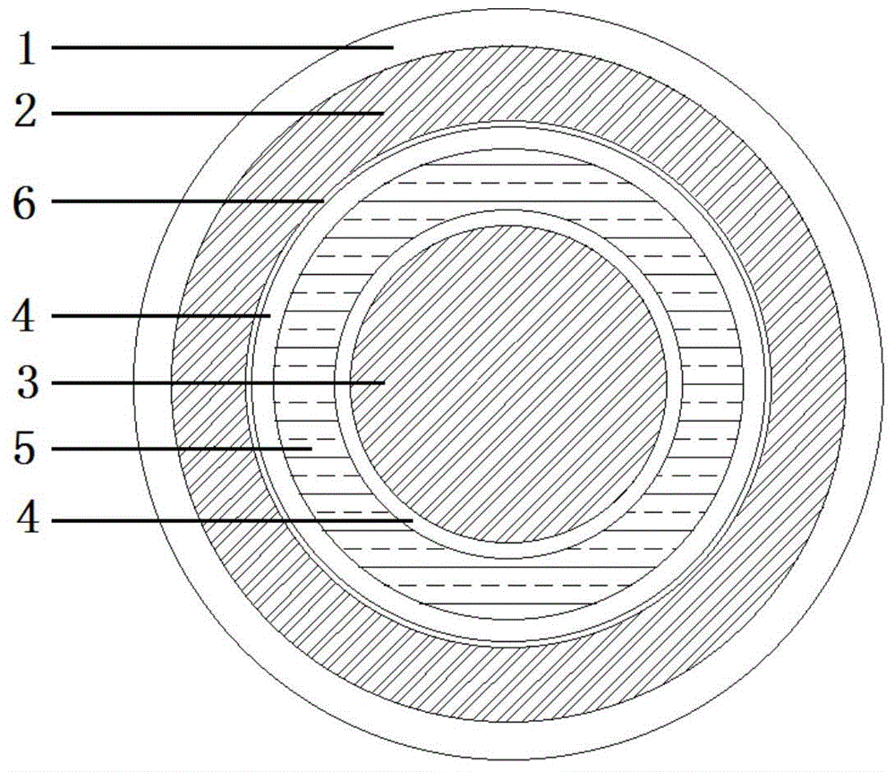
[0048] Such as figure 2 As shown, the differences between Embodiment 2 and Embodiment 1 are: 1) The number of poles of the stator and the mover of the motor are different; 2) The installation methods of the stator magnetic ring and the non-magnetic stator sleeve are different; 3) The mover core The molding methods are different. In this embodiment, the number of motor phases is m=4, the number of mover poles Pt=8, the number of stator poles Ps=6, the number of teeth contained in the mover cylinder Nt=9, the number of annular mover slots contained in the mover cylinder Qs=8, The number of stator magnetic rings contained in the mover cylinder is Ns ≥ 7. This embodiment includes a non-magnetic stator sleeve 1, a stator magnetic ring 2 is placed in the non-magnetic stator sleeve 1, and the stator magnetic ring 2 and The non-magnetic stator sleeve 1 is spliced ​​along the axial direction, the axial section of the stator magnetic ring 2 is trapezoidal, and the inner side of the no...


PUM


Abstract

The invention discloses a magnetic ring stator cylindrical linear switch reluctance motor which comprises a stator cylinder and a rotor cylinder. The stator cylinder comprises a stator magnetic ring and a non-magnetic stator sleeve, the stator magnetic ring is fixed to the non-magnetic stator sleeve or is coaxially spliced with the non-magnetic stator sleeve, and the stator cylinder is formed. The rotor cylinder comprises a rotor iron core, the rotor iron core is formed in a one-off mode or is formed by splicing a plurality of parts in the axial direction, rotor teeth, an annular rotor groove and a concentric rotor winding which is arranged in the annular rotor groove and winds around the axle wire of the rotor cylinder are arranged on the rotor iron core. According to the magnetic ring stator cylindrical linear switch reluctance motor, a stator yoke portion is omitted, the using amount of materials for manufacturing the iron core of the motor is reduced, the utilization rate of the iron core materials is improved, insulation between phases for the rotor groove is omitted, manufacturing technologies are simplified, utilization rate of the grooves is improved, and the magnetic ring stator cylindrical linear switch reluctance motor has the advantages of being high in propulsion density, simple and reliable in structure and the like.

Description

technical field [0001] The invention relates to a cylindrical motor, in particular to a cylindrical linear switched reluctance motor with a magnetic conduction ring stator. Background technique [0002] The linear motor directly converts electrical energy into mechanical energy of linear motion, which not only omits the intermediate transmission mechanism, but also reduces system loss, and is very suitable for linear direct drive systems. [0003] The flat linear motor is an open flat structure with both ends broken. There are transverse breaks on both sides of the motor core, which has obvious lateral edge effects, resulting in discontinuous distribution of the magnetic field in the motor and affecting the operating performance of the motor. The winding mode of the flat linear motor is similar to that of the rotary motor, and there are end windings. When the length of the iron core is long and the distributed winding form is used, the utilization rate of the winding is low,...

Claims


Application Information

Patent Timeline
IPC IPC(8): H02K41/03H02K1/34H02K1/12
Inventor 王道涵
Owner SHANDONG UNIV
Why Eureka
Eureka Blog
Learn More