Eureka AIR delivers breakthrough ideas for toughest innovation challenges, trusted by R&D personnel around the world.

Cylindrical linear switched reluctance motor with permanent magnet ring mover

A technology of switched reluctance motor and permanent magnet ring, applied in electromechanical devices, electrical components, electric components, etc., can solve the problem of low power density and propulsion force density, low utilization rate of ferromagnetic materials of motors, low running speed of linear motors, etc. problems, to achieve the effect of reducing dosage, simple and reliable structure, and good sealing performance

Active Publication Date: 2016-04-13
SHANDONG UNIV
View PDF5 Cites 0 Cited by
  • Summary
  • Abstract
  • Description
  • Claims
  • Application Information

AI Technical Summary

Problems solved by technology

However, due to the characteristics of the reluctance torque, the propulsive force density of the motor is low. Therefore, it is an urgent problem to be solved to improve the propulsive force density of the cylindrical linear motor.
In addition, the existing cylindrical linear switched reluctance motor has a mover yoke, the motor mover is heavy, only a part of the magnetic circuit is effectively used when the winding is energized, the utilization rate of the ferromagnetic material of the motor is low, and the power density and propulsion density are low
In addition, in many applications, the linear motor runs at a low speed, which is a low-speed high-thrust drive system. The motor has large magnetic flux leakage and high copper consumption during operation, resulting in low motor efficiency.
[0011] In the cylindrical linear switched reluctance motor, the use of the magnetic permeable ring structure can save the iron core yoke, reduce the mass of the mover, and increase the propulsion density, but there are still large magnetic flux leakage, low effective flux utilization and copper loss. high disadvantage

Method used


Image

  • Cylindrical linear switched reluctance motor with permanent magnet ring mover
  • Cylindrical linear switched reluctance motor with permanent magnet ring mover
  • Cylindrical linear switched reluctance motor with permanent magnet ring mover

Examples


Embodiment 1

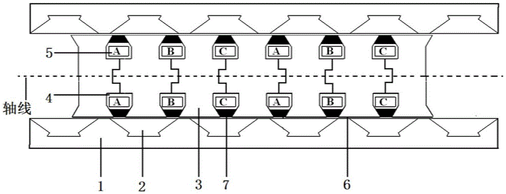
[0060] Such as figure 1 As shown, the number of motor phases in this embodiment is m=3, the number of mover poles Pt=6, the number of stator poles Ps=4, the number of mover teeth contained in the mover cylinder Nt=7, and the ring-shaped mover contained in the mover cylinder The number of slots is Qs=6, the number of permanent magnetic rings included in the mover barrel is Nm=6, and the number of magnetic conducting rings included in the stator barrel is Nr≥5. This embodiment includes a non-magnetic stator sleeve 1, a stator magnetic ring 2 is placed inside the non-magnetic stator sleeve 1, and the stator magnetic ring 2 is uniformly fixed inside the non-magnetic stator sleeve 1 along the axial direction. The axial section of the magnetic ring 2 is trapezoidal, and the bottom is processed into a special shape so as to be fixed with the non-magnetic stator sleeve 1, and the inner side of the non-magnetic stator sleeve 1 is provided with a mover core 3, and the mover core 3 and t...

Embodiment 2

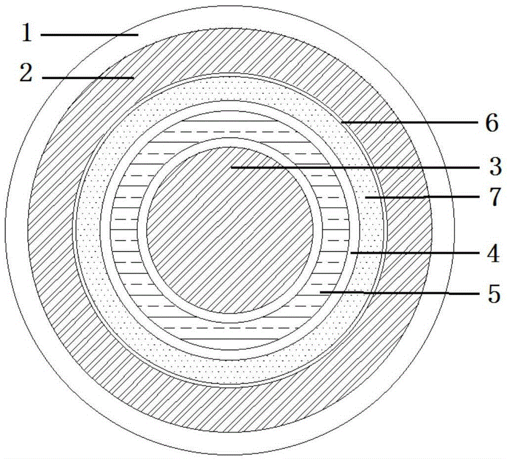
[0062] Such as figure 2 As shown, the difference between Embodiment 2 and Embodiment 1 is: 1) the number of poles of the stator and the mover of the motor are different; 2) the installation methods of the stator magnetic ring and the non-magnetic stator sleeve are different; 3) the mover core 4) The shapes of the permanent magnet rings are different. In this embodiment, the number of motor phases m=4, the number of mover poles Pt=8, the number of stator poles Ps=6, the number of mover teeth contained in the mover barrel Nt=9, and the number of annular mover slots included in the mover barrel is Qs=8, the number of permanent magnetic rings contained in the mover cylinder is Nm=8, and the number of magnetic conducting rings contained in the stator cylinder is Nr≥7. This embodiment includes a non-magnetic stator sleeve 1. A stator magnetic ring 2 is placed inside the non-magnetic stator sleeve 1. The stator magnetic ring 2 and the non-magnetic stator sleeve 1 are spliced ​​toge...


PUM


Abstract

The invention discloses a permanent magnet ring rotor cylindrical linear switch reluctance motor which comprises a stator cylinder and a rotor cylinder. The stator cylinder comprises a stator magnet guide ring and a non-magnet-guide stator sleeve. The stator magnet guide ring is fixed on the non-magnet-guide stator sleeve or is coaxially spliced with the non-magnet-guide stator sleeve to form the stator cylinder. The rotor cylinder comprises a rotor iron core which is once formed or is provided with a plurality of parts which are spliced in the axial direction, rotor teeth, an annular rotor groove and a rotor yoke part are arranged on the rotor iron core, and a set of rotor coil and a permanent ring are placed in the annular groove. According to the permanent magnet ring rotor cylindrical linear switch reluctance motor, the permanent magnet ring and the rotor coil are used for together providing an excitation magnetic field, the useful flux utilization rate is improved, a stator yoke part is omitted, the amount of used materials for manufacturing the motor iron core is lowered, the utilization rate of the iron core materials is improved, phase insulation is omitted in the rotor groove, the manufacturing process is simplified, the groove utilization rate is improved, and the advantages of being high in propulsion density, simple and reliable in structure and the like are achieved.

Description

technical field [0001] The invention relates to a cylindrical motor, in particular to a cylindrical linear switched reluctance motor with a permanent magnet ring mover. Background technique [0002] The linear motor directly converts electrical energy into mechanical energy of linear motion, which not only omits the intermediate transmission mechanism, but also reduces system loss, and is very suitable for linear direct drive systems. [0003] Cylindrical linear motor is a closed cylindrical mechanical structure. Since the motor core is closed, there is no lateral break and no lateral edge effect. The magnetic field inside the motor is evenly and continuously distributed along the circumference, and the propulsion force density is high. The inner stator slot of the cylindrical linear motor is ring-shaped, the motor winding is concentric winding, there is no end winding, the utilization rate of the winding is high, and the copper consumption is low during operation, which is ...

Claims


Application Information

Patent Timeline
Patent Type & Authority Patents(China)
IPC IPC(8): H02K41/03
Inventor 王道涵
Owner SHANDONG UNIV
Why Eureka
Eureka Blog
Learn More