
Fusion cage with in-line single piece fixation

A fusion device and a single technology, applied to internal fixers, fixators, surgical fixation nails, etc., can solve problems related to speech disorders, discomfort of patients with external appearance, etc., and achieve the effect of small puncture sites

Inactive Publication Date: 2014-02-05
DEPUY SYNTHES PROD INC
View PDF15 Cites 3 Cited by
  • Summary
  • Abstract
  • Description
  • Claims
  • Application Information

AI Technical Summary

Problems solved by technology

In general, the plate may be considered too prominent and its shape is sometimes uncomfortable for the patient and may be associated with dysphasia

Method used


Image

  • Fusion cage with in-line single piece fixation
  • Fusion cage with in-line single piece fixation
  • Fusion cage with in-line single piece fixation

Examples


Embodiment Construction

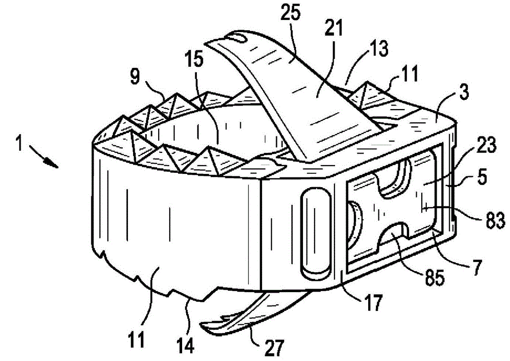
[0038]Referring now to Figures 1a and 1b, there is provided (claim 1) a zero-profile interbody fusion device comprising:

[0039] a) Intervertebral fusion cage 1, which includes a front wall 3 having a front surface 5 with a recess 7, a rear wall 9, a pair of side walls 11 connecting the front wall and the rear wall, an upper surface 13, and a lower surface 14 , and a through hole 15 extending from the upper surface to the lower surface, the cage has a front end 17,

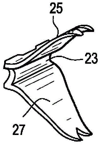
[0040] b) a staple 21 comprising a first crossbar 23 and a first fork 25 and a second fork 27 extending from the first crossbar 23,

[0041] wherein at least a portion of the first crossbar of the staple is disposed in a recess in the front surface of the front wall, and wherein the first tines extend above the upper surface of the cage and the second tines extend below the bottom surface of the cage,

[0042] Wherein the front surface is the front end of the cage.

[0043] The cage of Figure 1 differs from tha...


PUM


Abstract

Methods for securing a intervertebral cage to one or more levels of the spine with fixation. The fixation, which is typically a staple, is intended to be driven perpendicular to the proximal face of the cage and in-line with the inserter. After the cage is placed and positioned according to surgeon preference, a single piece fixation clip is then deployed and fixed in a manner that produces a zero-profile device.

Description

Background technique [0001] Spinal surgeons express a desire not to insert a plate on the anterior surface of the vertebral body and then place fixation devices such as bone screws through the plate. In general, the plate may be considered too prominent, and its shape is sometimes uncomfortable for the patient and may be associated with speech disorders. [0002] PCT Published Patent Application WO02 / 013732 (Bramlet) discloses an apparatus and method for fusing opposing vertebrae. The implant includes a body assembly and a retention member coupled to the body assembly. The retaining member includes a tang, wherein the tang is extendable from the body assembly. The method includes the step of inserting an implant between adjacent vertebrae using a retaining member of the implant in a first retracted configuration. The method also includes the step of configuring the retention member into a second extended configuration, wherein the retention member is in its second extended ...

Claims


Application Information

Patent Timeline
Patent Type & Authority Applications(China)
IPC IPC(8): A61F2/44
CPCA61F2002/30092A61F2002/30843A61B17/0682A61F2002/30604A61F2002/30161A61F2002/30787A61F2002/30904A61F2/4465A61F2002/4475A61F2002/30841A61F2002/30576A61F2310/00029A61B2017/0641A61F2002/30509A61F2002/30484A61F2002/30518A61B17/0642A61F2310/00161A61F2002/4623A61F2310/00017A61F2/4611A61F2310/00023A61F2002/30607A61F2002/30616A61F2002/2835A61F2002/30196A61F2002/30579A61F2002/30774A61F2002/4625A61F2002/30507A61F2/4603A61F2002/30593A61F2/44A61B17/70A61F2/28
Inventor T.加马彻J.奇尔德斯M.帕尔森K.弗拉赫蒂
Owner DEPUY SYNTHES PROD INC
Learn More