Air inlet structure for turbojet engine nacelle

A technology of nacelle and turbojet, which is applied in the direction of the air intake of the turbine/propulsion device, the combustion of the air intake of the power plant, engine components, etc., and can solve the problem of sealing defects, large thickness of the air intake lip, and the inner surface of the air intake Aerodynamic performance degradation and other issues, to achieve the effect of improving mechanical strength and reducing axial movement

Inactive Publication Date: 2014-02-05
AIRCELLE
View PDF8 Cites 2 Cited by
  • Summary
  • Abstract
  • Description
  • Claims
  • Application Information

AI Technical Summary

Problems solved by technology

[0013] This separation leads to degradation of the aerodynamic performance of the inner surface of the inlet and leads to sealing defects, which may be detrimental to the life and proper operation of the components (electric, hydraulic, pneumatic, etc.) located inside the inlet
[0014] In addition, the air intake lip with this type of construction is relatively thick especially in order to contribute to the mechanical strength of the assembly, which limits the implementation of electric deicing equipment with heating resistors
The implementation of this de-icing device is necessary for the air intake because, due to this structure of the air intake, it is difficult to be compatible with conventional hot air aerodynamic solutions

Method used


Image

  • Air inlet structure for turbojet engine nacelle
  • Air inlet structure for turbojet engine nacelle
  • Air inlet structure for turbojet engine nacelle

Examples


Embodiment Construction

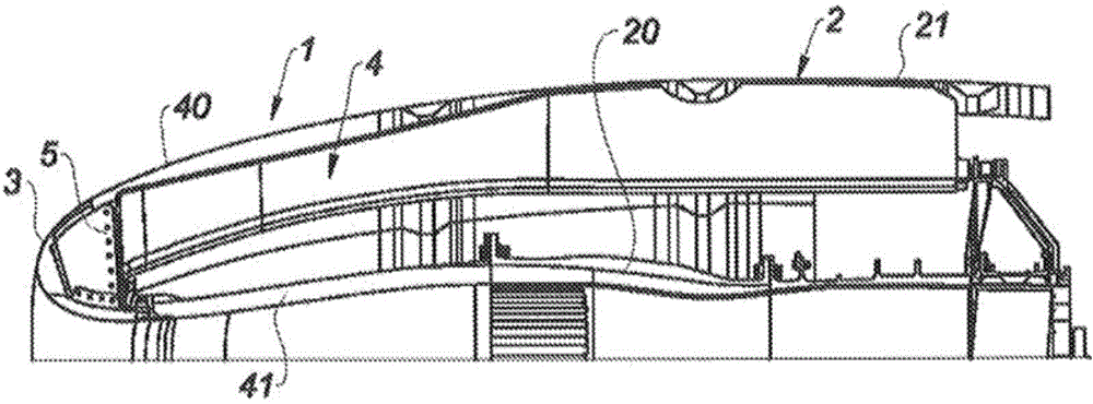
[0044] The nacelle usually has a generally tubular structure that includes an air intake ( figure 1 ), the middle section surrounding the turbojet fan, and the downstream section accommodating the thrust reverser device and surrounding the turbojet engine combustion chamber. The nacelle usually ends in a jet nozzle, and the outlet of the jet nozzle is located downstream of the turbojet engine.

[0045] figure 1 A longitudinal sectional view of the air intake structure 1 according to the prior art is shown.

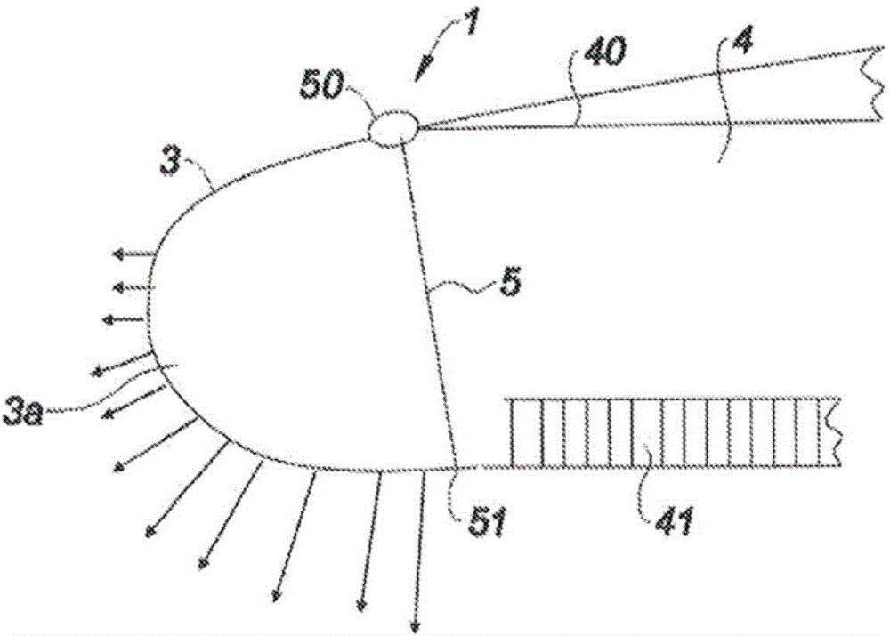
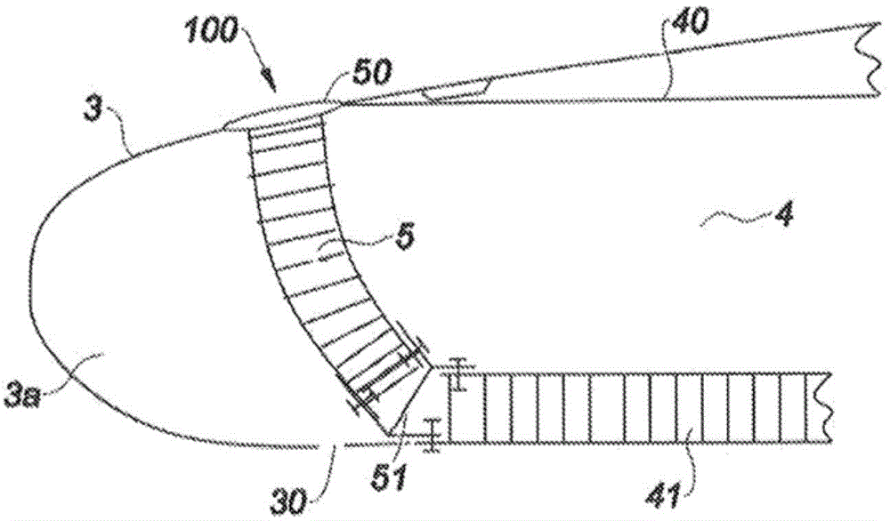
[0046] The air intake structure 1 is located upstream of the middle section 2 of the nacelle, and includes an air intake lip 3 on the one hand, suitable for allowing the air to be supplied to the turbine engine to be optimally captured towards the turbojet engine; on the other hand, it includes a downstream structure 4. The lip is attached to the downstream structure 4 and guides air appropriately to the fan blades.

[0047] More specifically, the air inlet structure 1 generally ...


PUM


Abstract

The invention relates to an air inlet structure (100) for a turbojet engine nacelle, comprising: (i) at least one stationary internal wall (41) intended to be attached to at least one element (20) of a mid-section (2) of the nacelle, and (ii) at least one longitudinal external wall (40) extended by an air inlet lip (3) connected to the stationary internal wall. The structure is characterised in that at least the air-inlet-lip-forming portion is provided with means (30, 60) for depressurising at least part of the lip.

Description

Technical field [0001] The invention relates to an air inlet structure for a turbojet engine nacelle, which can guide airflow to a fan of the turbojet engine. Background technique [0002] The aircraft is propelled by one or more propulsion assemblies, which include turbojet engines housed in a tubular nacelle. Each propulsion component is attached to the aircraft by rods usually located under the wings or at the fuselage. [0003] The nacelle usually has a structure that includes an intake port upstream of the engine, a middle section surrounding the turbojet engine fan, and a downstream section containing a thrust reverser device and surrounding the turbojet engine combustion chamber. The nacelle usually It ends in a jet nozzle, where the outlet of the nozzle is located downstream of the turbojet engine. [0004] The air intake includes an air intake lip on the one hand, adapted to allow optimal capture of the air that needs to be supplied to the fan and internal compressor of th...

Claims


Application Information

Patent Timeline
Patent Type & Authority Applications(China)
IPC IPC(8): B64D33/02
CPCB64D2033/0286B64D2033/0226B64D33/02Y10T137/0536F02C7/04
Inventor 尼古拉斯·德泽斯特
Owner AIRCELLE
Why Eureka
Try Eureka